Video display method, video signal processing apparatus, and video display apparatus

a video display and video signal technology, applied in the field of video display methods, video signal processing apparatus, and video display apparatus, can solve the problems of easy decrease of area perception or flicker, etc., and achieve the effect of improving the display characteristics of moving images without decreasing the luminance of display screen

Inactive Publication Date: 2008-04-03
SEIKO EPSON CORP
View PDF6 Cites 18 Cited by
  • Summary
  • Abstract
  • Description
  • Claims
  • Application Information

AI Technical Summary

Benefits of technology

[0008]An advantage of some embodiments of the invention is that it provides a video display method and a video signal pr...

Problems solved by technology

Thus, there is a possibility that the area is perceived or causes flicker.
In add...

Method used


Image

  • Video display method, video signal processing apparatus, and video display apparatus
  • Video display method, video signal processing apparatus, and video display apparatus
  • Video display method, video signal processing apparatus, and video display apparatus

Examples


first embodiment

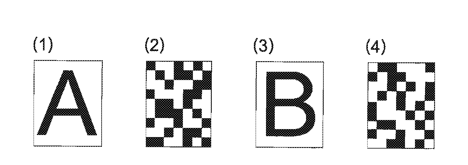
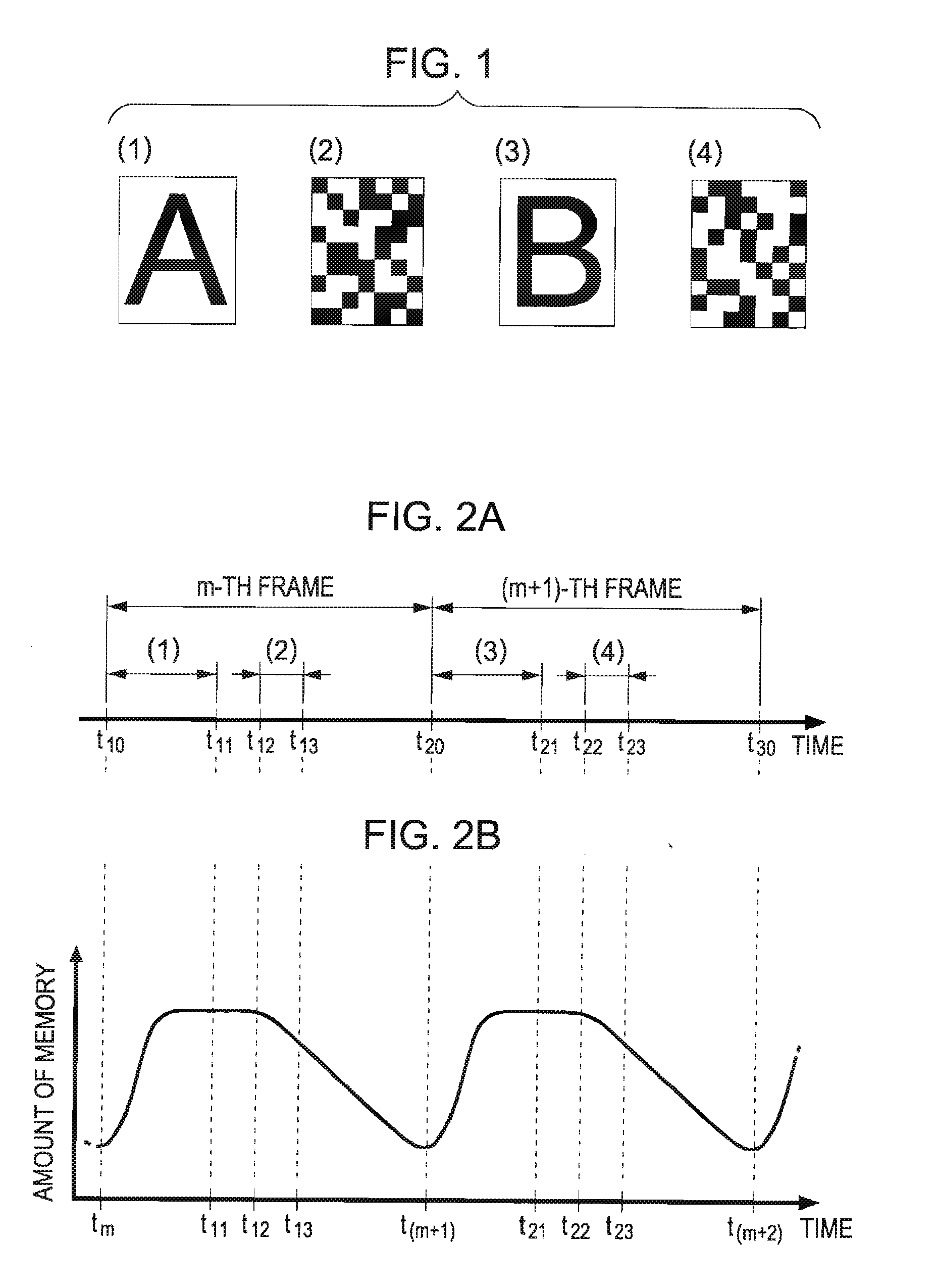
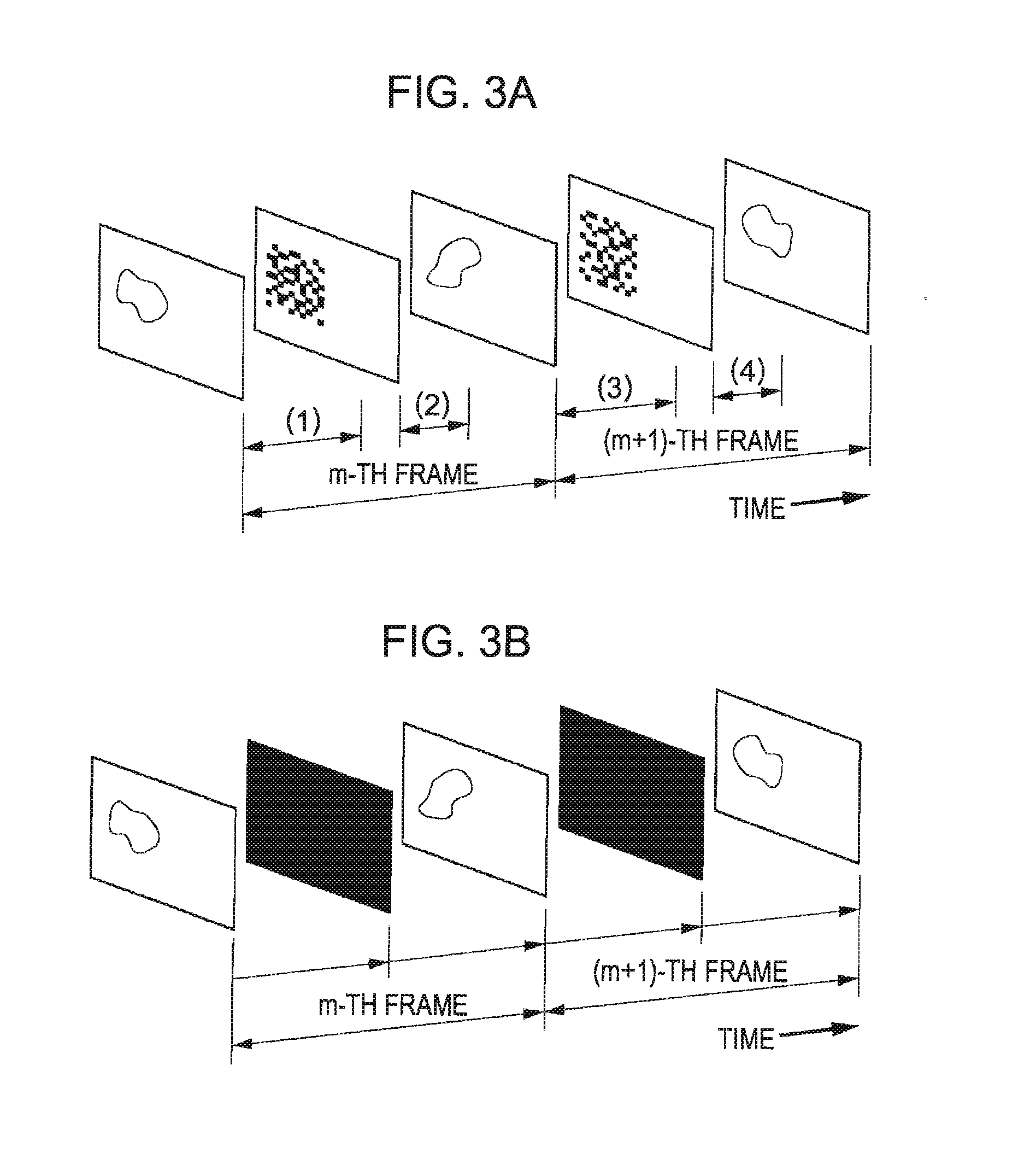
[0041]FIG. 1 is a diagram showing an image display sequence in a video display method according to a first embodiment of the present invention. FIGS. 2A and 3A are diagrams showing a display period of images as an example. FIG. 2B is a diagram showing a viewer's perception of the display.

[0042]In FIG. 1, an image denoted by “(1)” is a scan screen, which is displayed as a frame (referred to as “m-th frame” for the convenience of description), among scan screens on the basis of video signals supplied in a non-interlaced format (sequential scanning). An image denoted by “(3)” is a scan screen displayed in accordance with the next frame (referred to as “(m+1)-th frame”).

[0043]Here, a case where a non-interlaced format is used is described. The number of frames per second is, for example, 60, and a period of one frame is 16.7 milliseconds (a reciprocal number of 60 Hz).

[0044]In this embodiment, as shown in FIGS. 2A and 3A, a screen (1) defined by a video signal is displayed from the star...

second embodiment

[0094]A second embodiment of the invention will now be described. Hereinafter, descriptions for embodiments of the second embodiment common to those of the first embodiment will be omitted as needed.

[0095]FIG. 12 is a diagram of a video signal processing apparatus for implementing a video display method according to the second embodiment.

[0096]As shown in the figure, the video signal processing apparatus 10b processes a video signal Vid supplied from an external higher-level device (not shown) and supplies the processed video signal to a display unit 20. For example, the video signal processing apparatus 10b that is connected to an input terminal of the display unit 20 as an adaptor includes a multiple-speed frame generating unit 12, a mask pattern generating unit 16, and a selector 18.

[0097]The reasons that the video signal Vid transmitted from the higher-level device is input to the mask pattern generating unit 16 are as follows. First, timing for generation of mask patterns is de...


PUM


Abstract

A video display method is used in a display device that displays images in correspondence with frames or fields defined by a video signal on the basis of the video signal. The video display method includes a step of generating mask patterns in correspondence with frames or fields defined by the video signal such that the mask patterns corresponding to consecutive frames or fields defined by the video signal are different from each other. The mask patterns include randomly arranged black and white dots or patterns. At least one of the images is displayed on the basis of the video signal and then at least one of the generated mask patterns is displayed.

Description

BACKGROUND[0001]1. Technical Field[0002]The present invention relates to technology for reducing motion blur in a case where a video signal such as a television signal is displayed by using a liquid crystal device or the like.[0003]2. Related Art[0004]Liquid crystal devices, active matrix organic EL devices, and the like are hold-type display devices in which a display image is maintained over one frame period (16.7 milliseconds). In the hold-type display devices, when transition to the next frame is made, the image of the previous frame is retained as a retinal afterimage. Accordingly, when there is a motion being shown in images displayed in consecutive frames, a moving area is perceived to be unnatural or an outline thereof is perceived to be blurred. In other words, motion blur occurs.[0005]On the other hand, CRTs are impulse-type display devices in which an image is displayed momentarily. In the impulse-type display devices, since retinal retention of an image displayed in the ...

Claims


Application Information

Patent Timeline
IPC IPC(8): H04N9/12
CPCG09G3/32G09G3/36G09G2310/0251H04N9/3197G09G2320/0261G09G2320/106H04N9/312G09G2320/0257
Inventor NAGAISHI, MICHIHIROKOMATSU, TOYOAKI
Owner SEIKO EPSON CORP
Why Eureka
Try Eureka