Foaming Agent for Subterranean Formations Treatment, and Methods of Use Thereof

a technology of foaming agent and subterranean formation, applied in the field of fluids, can solve the problems of increasing difficulty in formulating stable foaming fluid with rheological properties suitable for fracturing operations, phase separation and loss of fluid viscosity, and increase the difficulty of fracturing operations

Inactive Publication Date: 2008-04-03
SCHLUMBERGER TECH CORP
View PDF9 Cites 58 Cited by
  • Summary
  • Abstract
  • Description
  • Claims
  • Application Information

AI Technical Summary

Problems solved by technology

The ability to formulate stable energized fluids with rheological properties suitable for fracturing operations becomes increasingly difficult as the temperature of the subterranean formation increases.
The matter is worsened when carbon dioxide is present in the gas phase, since carbon dioxide exhibits high solubility in aqueous solutions.
The high solubility of carbon dioxide facilitates mass transfer between bubbles and accelerates foam-destabilizing mechanisms such as so-called Ostwald ripening, which ultima

Method used


Image

  • Foaming Agent for Subterranean Formations Treatment, and Methods of Use Thereof
  • Foaming Agent for Subterranean Formations Treatment, and Methods of Use Thereof
  • Foaming Agent for Subterranean Formations Treatment, and Methods of Use Thereof

Examples


example 1

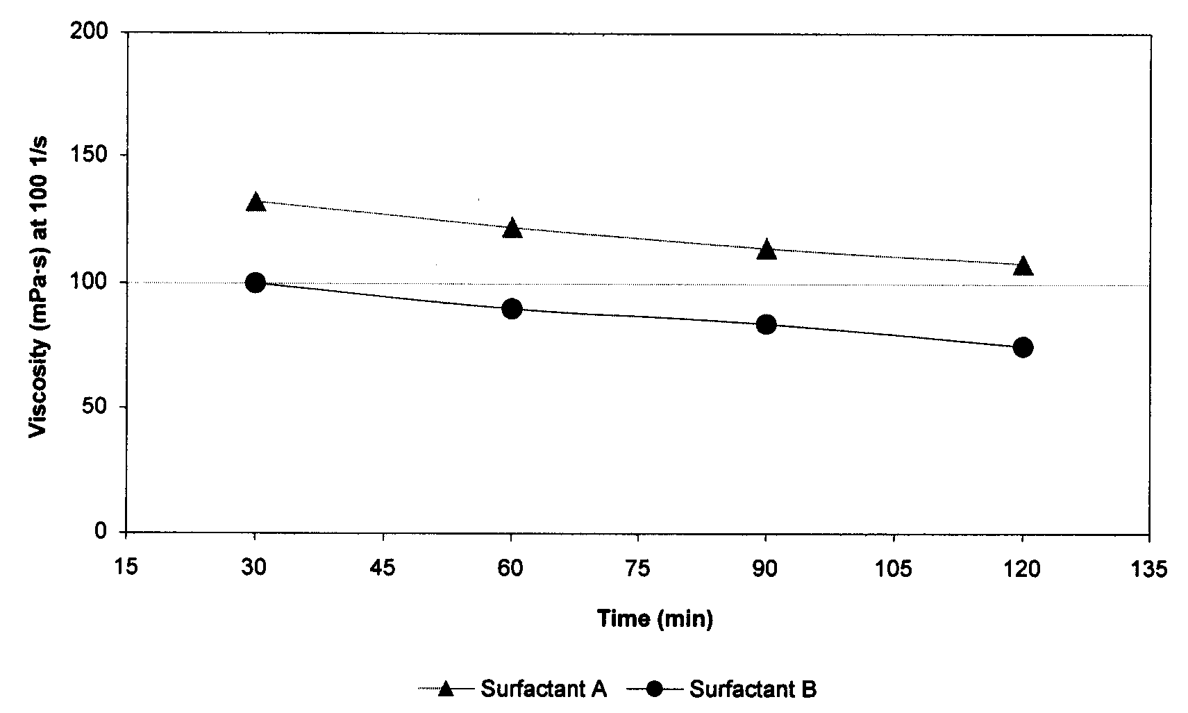
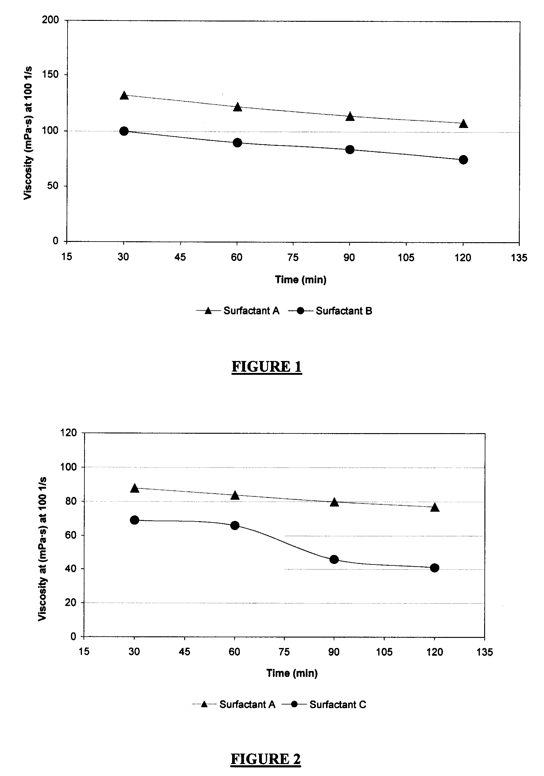
[0074]Guar-based fluids energized with N2 were tested using Surfactants A and B at approximately 120° C. These energized fluids contained 0.6 wt % guar, 1.0 vol % surfactant A or B, and 0.1 wt % tetramethyl ammonium chloride, in aqueous solutions. Guar was added in a slurry form in which guar and diesel solvent each accounted for 50 wt % of the slurry. Foam quality was 70%, and the temperature was constant at about 120° C. The viscosity was measured at 100 s−1. The results are shown in FIG. 1, and indicate that Surfactant A provides better foam stability compared with Surfactant B at 120° C. in N2 foams. The sample using Surfactant A contained less active surfactant as compared with Surfactant B (30 wt % vs. 50 wt %) but the viscosity was approximately 35% greater for that for the sample using Surfactant B.

example 2

[0075]Guar-based fluids foamed with CO2 were tested using Surfactants A and C at approximately 120° C. The fluids contained 0.6 wt % guar, 1.0 vol % Surfactant A or C, and 0.1 wt % tetramethyl ammonium chloride. The results are presented in FIG. 2. FIG. 2 shows that Surfactant A provides significantly better foam stability compared with Surfactant C at 120° C. in CO2 foams. It can be seen that the foam viscosity measured at 100 s−1 by using Surfactant C fell below 50 mPa·s after 75 min. It is commonly accepted that 50 mPa·s is the minimum viscosity for fracturing applications. With Surfactant A, much greater viscosity was achieved even after 2 hours. Foam quality was 70%, and the temperature was constant at about 120° C.

example 3

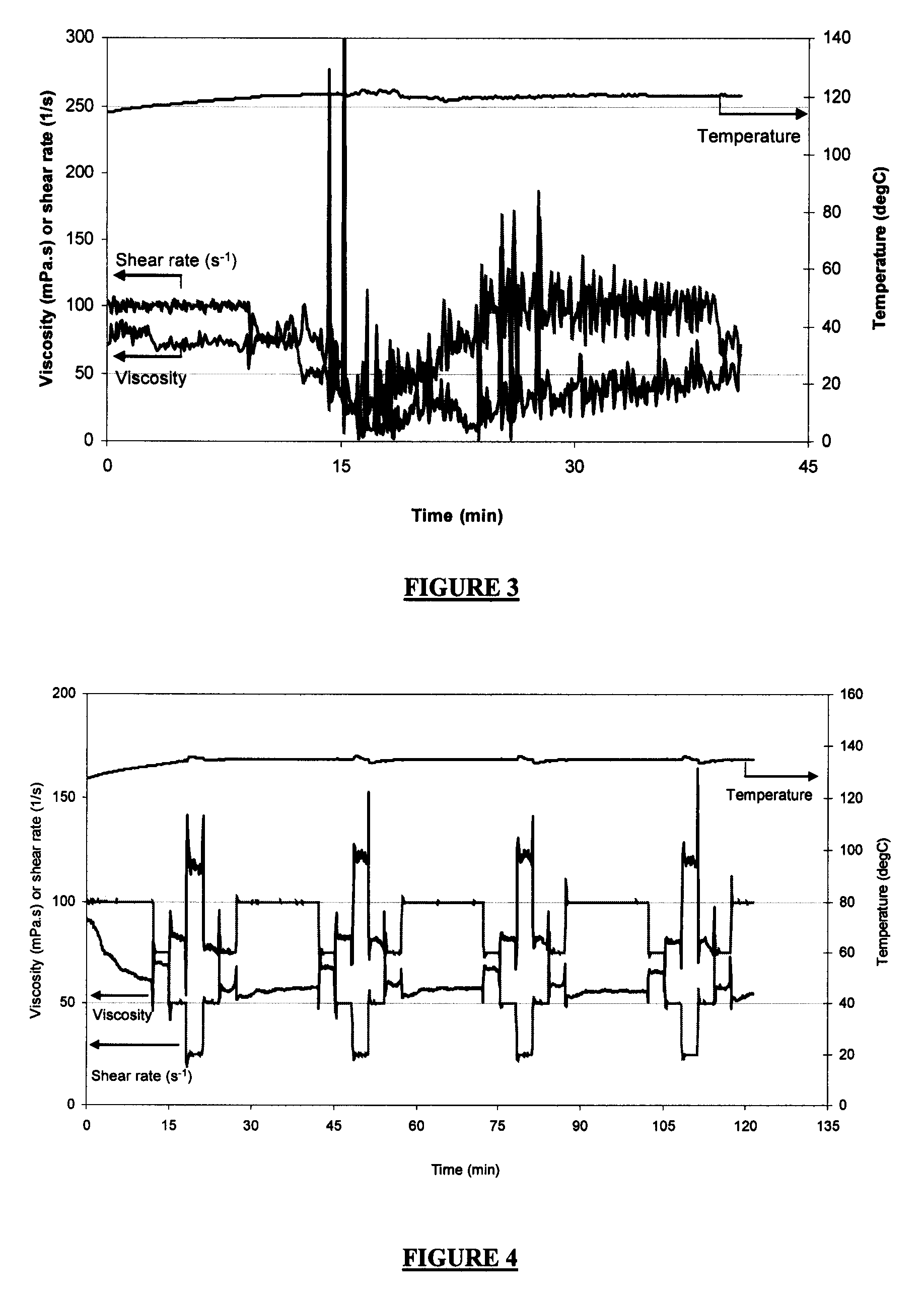
[0076]A guar-based fluid foamed with N2 was tested using Surfactant D at approximately 120° C. The fluid contained 0.36 wt % guar, 1.0 vol % Surfactant D, and 0.1 wt % tetramethyl ammonium chloride. Guar was added in a slurry form in which guar and mineral oil each accounted for 50 wt % of the slurry. Foam quality was approximately 70% at time 0 min. The density and shear rate fluctuated as a result of the instable foam. The results are presented in FIG. 3. FIG. 3 illustrates that Surfactant D, a C12 sulfate, was unable to create a stable foam at 120° C. in N2 foams, and may suggest that the ethylene oxide units in Surfactant A may play an important role in providing greater foam stability. At the same gel loading, Surfactant A maintained the foam viscosity above 50 mPa·s at 100 s−1 for over 2 hours (see in FIG. 8).


PUM

PropertyMeasurementUnit
Temperatureaaaaaaaaaa
Fractionaaaaaaaaaa
Fractionaaaaaaaaaa

Abstract

A wellbore treatment fluid is formed from an aqueous medium, a gas component, a viscosifying agent, and a surfactant. The surfactant is represented by the chemical formula:
[R—(OCH2CH2)m—Oq—YOn]pX
wherein R is a linear alkyl, branched alkyl, alkyl cycloaliphatic, or alkyl aryl group; O is an oxygen atom; Y is either a sulfur or phosphorus atom; m is 1 or more; n is a integer ranging from 1 to 3; p is a integer ranging from 1 to 4; q is a integer ranging from 0 to 1; and X is a cation. The fluid may be used in treating a subterranean formation penetrating by a wellbore by introducing the fluid into the wellbore. The fluid may be used in fracturing a subterranean formation penetrated by a wellbore by introducing the fluid into the formation at a pressure equal to or greater than the fracture initiation pressure.

Description

[0001]This application claims the benefit of U.S. Provisional Patent Application No. 60 / 827,324, filed Sep. 28, 2006, which is incorporated herein by reference in its entirety.BACKGROUND OF THE INVENTION[0002]This invention relates to fluids used in treating a subterranean formation. In particular, the invention relates to aqueous energized wellbore treatment fluids, and methods of forming and using such fluids.[0003]Various types of fluids are used in operations related to the development and completion of wells that penetrate subterranean formations, and to the production of gaseous and liquid hydrocarbons from natural reservoirs into such wells. These operations include perforating subterranean formations, fracturing subterranean formations, modifying the permeability of subterranean formations, or controlling the production of sand or water from subterranean formations. The fluids employed in these oilfield operations are known as drilling fluids, completion fluids, work-over fl...

Claims


Application Information

Patent Timeline
IPC IPC(8): C09K8/60
CPCC09K8/536C09K8/68C09K8/703C09K2208/26C09K8/90C09K8/905C09K8/94C09K8/74
Inventor LIN, LIJUNABAD, CARLOSDROCHON, BRUNOKUBALA, GREGORYSCHAFER, LAURAPENA, ALEJANDROBUOY, RAMSEY
Owner SCHLUMBERGER TECH CORP
Why Eureka
Try Eureka