Fluid-Tight Slide Fastener

a slide fastener and fluid-tight technology, applied in the field of sliding fasteners, can solve the problems of tape weakening, slide fasteners tapes that do not always show satisfactory mechanical properties, etc., and achieves stronger coupling, and improved resistance to delamination.

Inactive Publication Date: 2008-04-10
RIRI GROUP
View PDF36 Cites 3 Cited by
  • Summary
  • Abstract
  • Description
  • Claims
  • Application Information

AI Technical Summary

Benefits of technology

[0030] It has been surprisingly found that a fastener with such inner textile layer has improved resistance to delamination. It is considered that improved resistance to delamination is due to said irregular, rough surface of the yarn, giving a stronger coupling with the fluid-barrier layer. More in particular, it has been found that ends or loops of the fibers, protruding from the ideal diameter of the yarn, remain embedded in the thermoplastic elastomer material of the fluid-barrier layer enhancing the resistance to delamination.
[0031] In a preferred embodiment, said thermoplastic elastomer material is coupled to the textile layer in a melted state, and the above effect is obtained, i.e. irregularities of the

Problems solved by technology

However, although effectively fluid-tight at the teeth—outer barrier layer interface, slide fasteners of the above-described type exhibit a drawback in that they do not always show satisfactory mechanical properties, in particular at the interface between the inner layer and the outer layer of the tapes.
This separati

Method used


Image

  • Fluid-Tight Slide Fastener
  • Fluid-Tight Slide Fastener
  • Fluid-Tight Slide Fastener

Examples


example 1

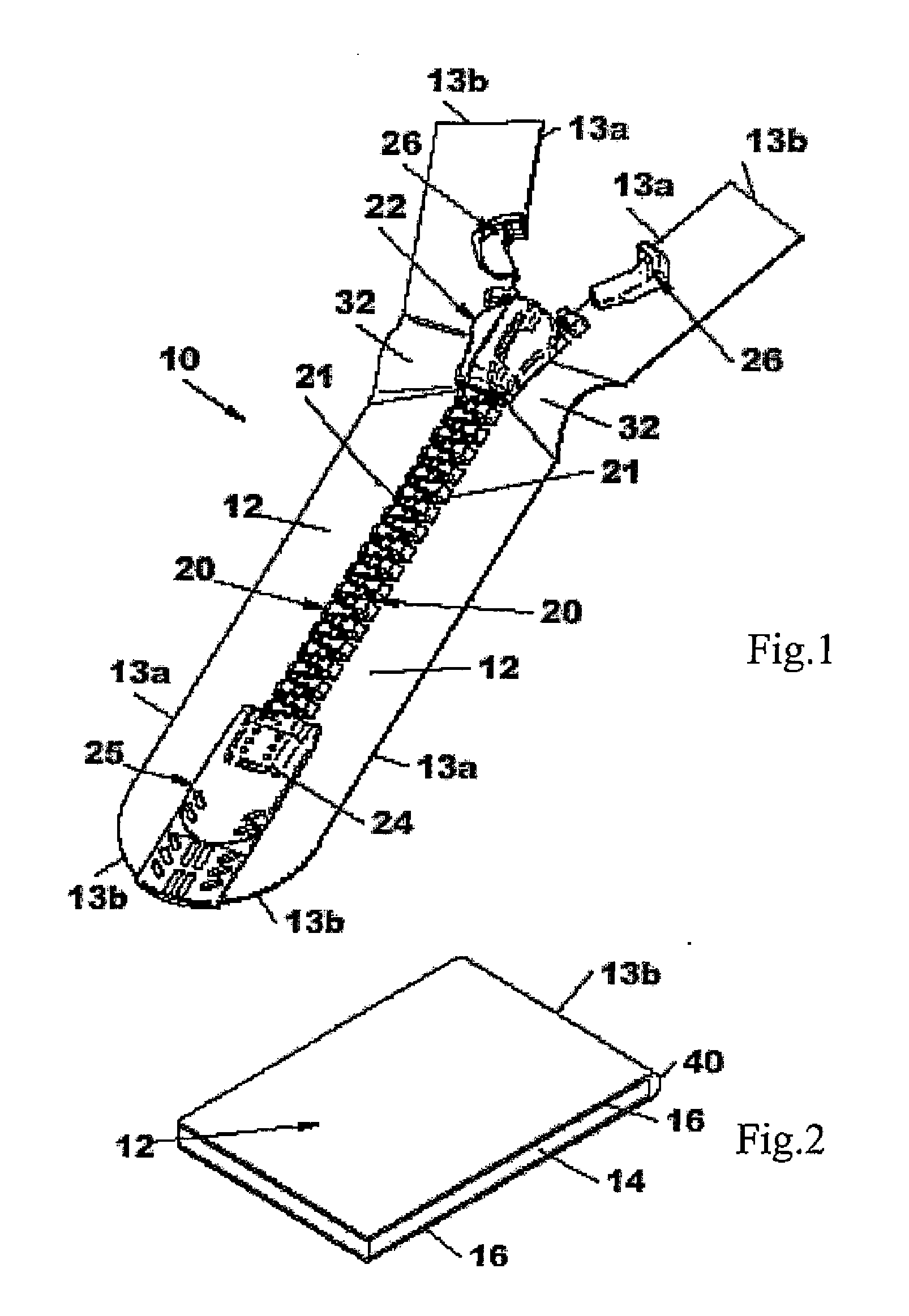
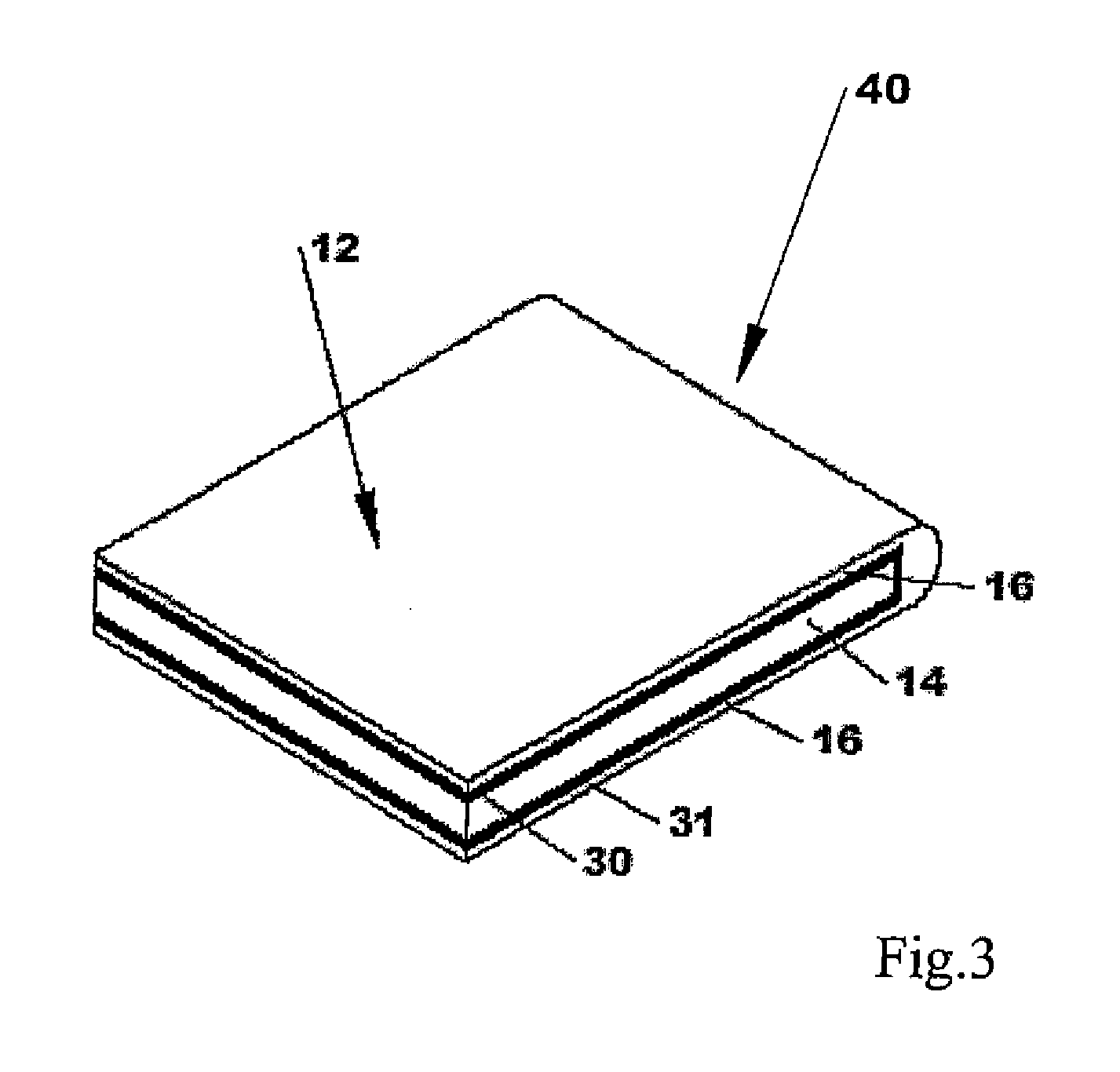
[0068] Strips of PE fibers were fully coated with a layer of fluid-barrier material (a TPE-U material) by means of a conventional extrusion head. The extrusion of the fluid-barrier material from said head was performed in a conventional way according to the procedure suggested by the manufacturer.

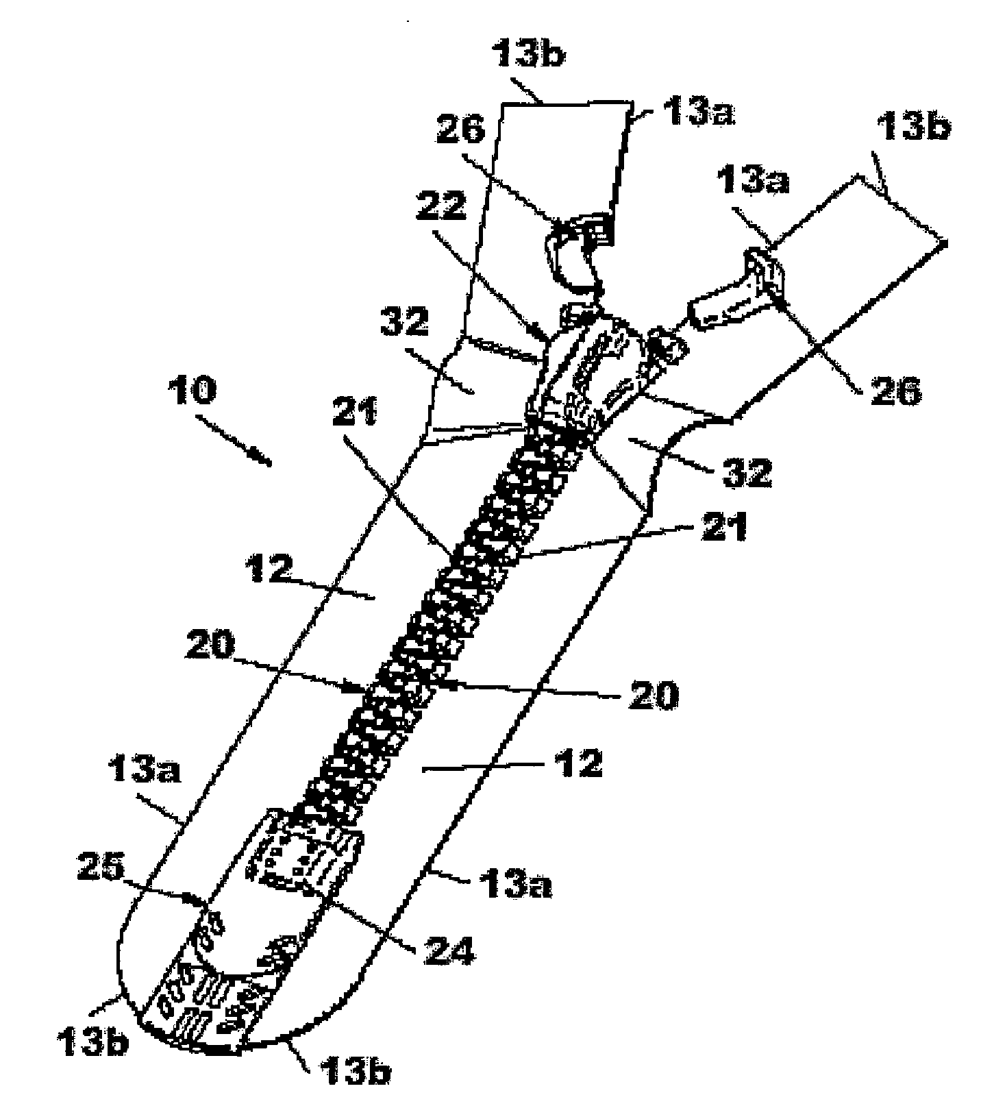
[0069] The coated strips were then equipped each with a plurality of rows of aligned teeth along a longitudinal edge thereof, said rows being set at a predetermined distance to each other. The teeth were each made from a blend of ABS and PA. The teeth application was performed by injection overmolding the teeth material onto said longitudinal edge of the coated strips in a conventional way (according to the procedure suggested by the manufacturer). The coated strip equipped with said rows of aligned teeth were then heat cut transversally along consecutive rows of aligned teeth to obtain a plurality of tapes of the same dimensions, wherein each tape was equipped with a row of aligned teeth....

example 2

[0080] A plurality of slide fasteners were manufactured using the same procedure disclosed in example 1. However, in this example, the fluid barrier material covering the strips of textile material was made of TPE-E including yellow pigments and the material for the teeth was PBT.

[0081] The slide fasteners so obtained were tested for their resistance to delamination of the layered structure of the tapes using the same procedure discussed above in example 1. However, in this example, all samples according to the invention to be tested were engraved substantially at the same position on the tape surface.

[0082] The results are shown in the following table 2 as a mean of minimum load values obtained from tested samples.

TABLE 2Minimum load (in Kg) necessary to obtain delaminationAfterAfterAfterAfterAfterBefore1st2nd3rd4th5thwashingwashingwashingwashingwashingwashingSamplescyclescyclecyclecyclecyclecycle1.51.31.31.21.01.0

[0083] As can be seen from the above table 2, the slide fastener...

example 3

[0087] In this example, slide fasteners were prepared by using an adhesive for bonding the layers of the tapes.

[0088] In particular, it was carried out a variant of the procedure discussed above in example 1 according to which an adhesive layer (polyurethane resin) was first applied on the opposite surfaces of strips of PE, by soaking the strips in an adhesive dispersion, and then the strips provided with the adhesive were covered with a TPE-U fluid-barrier layer according to the procedure of example 1.

[0089] The procedure of example 1 was also followed after coating the strips, thereby obtaining a plurality of slide fasteners which were tested for their resistance to delamination of the layered structure of the tapes.

[0090] It was found that, thanks to the presence of adhesive in-between, the fluid-barrier layer and the textile layer of the respective tape were bonded extremely strong to each other and as a result no delamination of such layers was observed both before and after...


PUM

PropertyMeasurementUnit
Weight ratioaaaaaaaaaa
Distanceaaaaaaaaaa
Thermoplasticityaaaaaaaaaa

Abstract

Fluid-tight slide fastener (10) comprising a pair of tapes (12), each tape (12) having a layered structure comprising an inner reinforcing textile material layer (14) enveloped in a fluid barrier layer (16) made of a thermoplastic elastomer material (TPE), each tape (12) exhibiting a row (20) of aligned teeth (21) made of a thermoplastic material on at least a portion of one of the long sides (13a) thereof, the rows (20) of aligned teeth (21) of said pair of tapes (12) facing each other and being associated to opposite stops (24,26), and a slider (22) slidable between said opposite stops (24,26) for engaging in a fluid-tight way or disengaging said aligned teeth (21) respectively, characterized in that said textile material for the inner reinforcing layer (14) is chosen among polyester (PE), preferably PET, polyamide (PA) and their blends or copolymers; said thermoplastic elastomer material (TPE) for the fluid barrier layer (16) is chosen between thermoplastic elastomer polyurethane (TPE-U) and thermoplastic elastomer polyester (TPE-E), and said thermoplastic material for the teeth (21) is chosen among polybutylene terephthalate (PBT), acrylonitrile butadiene styrene (ABS), polyamide (PA) and their blends or copolymers.

Description

FIELD OF APPLICATION [0001] The present invention, in its most general aspect, refers to a slide fastener. [0002] In particular, the invention refers to a fluid-tight slide fastener, i.e. a slide fastener that is impermeable to fluids. [0003] In the following description, the term “fluid-tight” refers to a seal or material that is resistant to the passage of liquids, in particular water, and / or gases, for example air, even when put under a considerable pressure strain, for example a pressure difference between the interior and the exterior sides of a slide fastener of up to about 2 bars. [0004] More in particular, the present invention refers to a fluid-tight slide fastener of the type comprising a pair of impermeable tapes, each tape having a layered structure comprising an inner layer of a reinforcing textile material strip and an outer layer of fluid barrier material enveloping said inner layer, each tape also comprising a row of aligned teeth on at least a portion of one of the ...

Claims


Application Information

Patent Timeline
IPC IPC(8): A44B19/32A44B19/42
CPCA44B19/32A44B19/42Y10T24/253Y10T24/2539Y10T24/2529Y10T29/49782Y10T24/2514
Inventor COSSUTTI, LIVIOBUTZ, MARC
Owner RIRI GROUP
Why Eureka
Try Eureka