

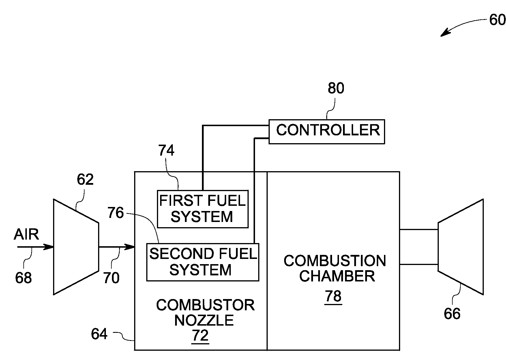
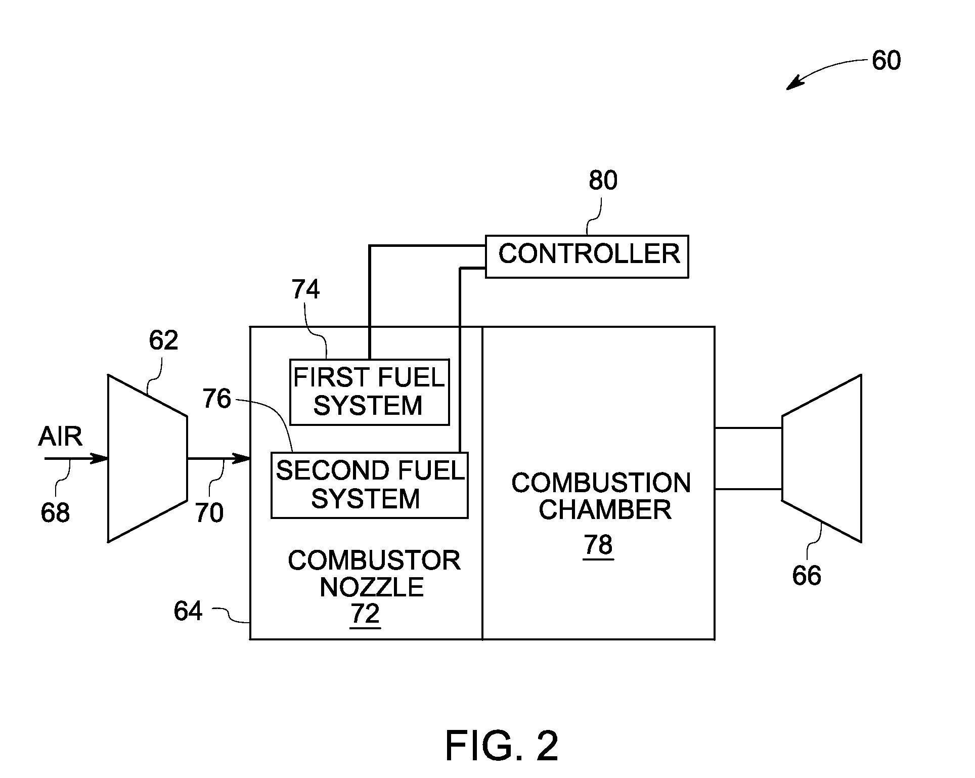
Combustor nozzle for a fuel-flexible combustion system
a combustion system and combustor technology, applied in the field of combustion systems, can solve the problems of difficult design of combustor, limited fuel flexibility in order of combustion systems, and small window of operability of such combustion systems
- Summary
- Abstract
- Description
- Claims
- Application Information
AI Technical Summary
Problems solved by technology
Method used
Image

Examples
Embodiment Construction
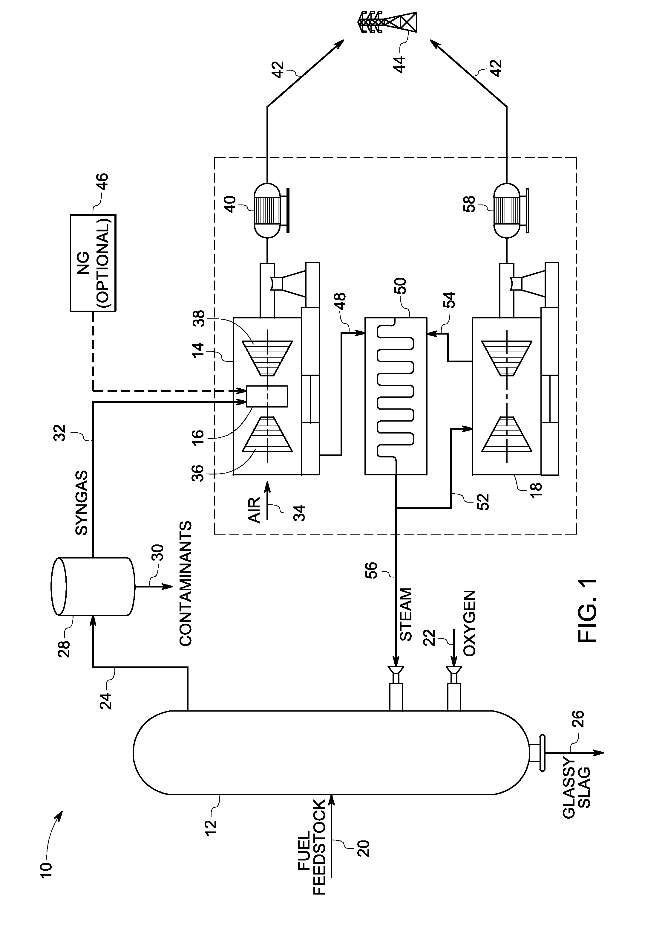
[0019]As discussed in detail below, embodiments of the present technique function to provide a fuel-flexible combustion system that will work with a variety of fuels while having reduced emissions. In particular, the present technique employs a combustor nozzle that operates with, for example, natural gas and a wide range of syngas fuels by switching between lean premixed and diffusion combustion modes based upon a desired or required volumetric flow rate of the fuel feedstock. Turning now to the drawings and referring first to FIG. 1, an integrated coal gasification combined cycle (IGCC) system 10 is illustrated. The IGCC system 10 includes a gasifier 12 and a gas turbine 14 coupled to the gasifier 12. Further, the gas turbine 14 includes a fuel-flexible combustion system 16 configured to combust a fuel stream from the gasifier 12 to produce electrical energy. In addition, the IGCC system 10 includes a steam turbine 18 coupled to the gas turbine 14 and configured to generate electr...
PUM
 Abstract
Description
Claims
Application Information