Regeneration method of etching solution, an etching method and an etching system

a technology of etching solution and etching system, which is applied in the direction of chemistry apparatus and processes, separation processes, filtration separation, etc., can solve the problems of reducing the etching rate resulting from the raised concentration of silicon compounds clogging of filters, and extremely inefficient performance, so as to reduce the cost of regenerating treatment and eliminate silicon compounds produced in the etching solution. , the effect of extremely efficient removal

Inactive Publication Date: 2008-04-17
APPRECIA TECH
View PDF3 Cites 32 Cited by
  • Summary
  • Abstract
  • Description
  • Claims
  • Application Information

AI Technical Summary

Benefits of technology

[0012]Accordingly, the subject of the present invention is to eliminate weak points of said conventional methods and to provide a regenerating method of etching solution, an etching method and an etching system which can remove silicon compounds in the etching solution constantly at a high removal rate through use of filters with filter elements of a high silicon removal rate with already deposited silicon compounds beyond a certain amount level, having been used over a certain period of time, can eliminate silicon compounds produced in etching solution extremely efficiently, being more suitable for an industrial process, and can reduce the cost for regenerating treatment of etching solution.

Problems solved by technology

Said method, however, involves a problem of decreased etching rates resulting from raised concentrations of silicon compounds in the etching solution as a consequence of repeated treatments with the same etching solution.
However, the methods or the systems for regenerating etching solution described in JP 3-20895 B (Patent Document 1), JP 9-219388 A (Patent Document 2) and JP 6-310487 A (Patent Document 3) need to remove silicon compounds deposited within the filter by way of water washing, etc., since silicon compounds which gradually deposit within the filter during operation cause filters to clog.
For such removal, operation of the system must be stopped periodically, leading to extremely inefficient performance.
Namely, it was found that the removal amount of silicon compounds by a new filter element with no deposited silicon compounds or a filter element with no deposited silicon compounds right after rinsing for removal of deposited silicon compounds was extremely small, and the removal amount of silicon compounds increases operating time of the filter up to even more than 10 times. However, if the filter continues to be operated beyond a certain time range, the filter clogged and became unserviceable.

Method used


Image

  • Regeneration method of etching solution, an etching method and an etching system
  • Regeneration method of etching solution, an etching method and an etching system
  • Regeneration method of etching solution, an etching method and an etching system

Examples


example

Example 1

[0033]The following is an example of the present invention.

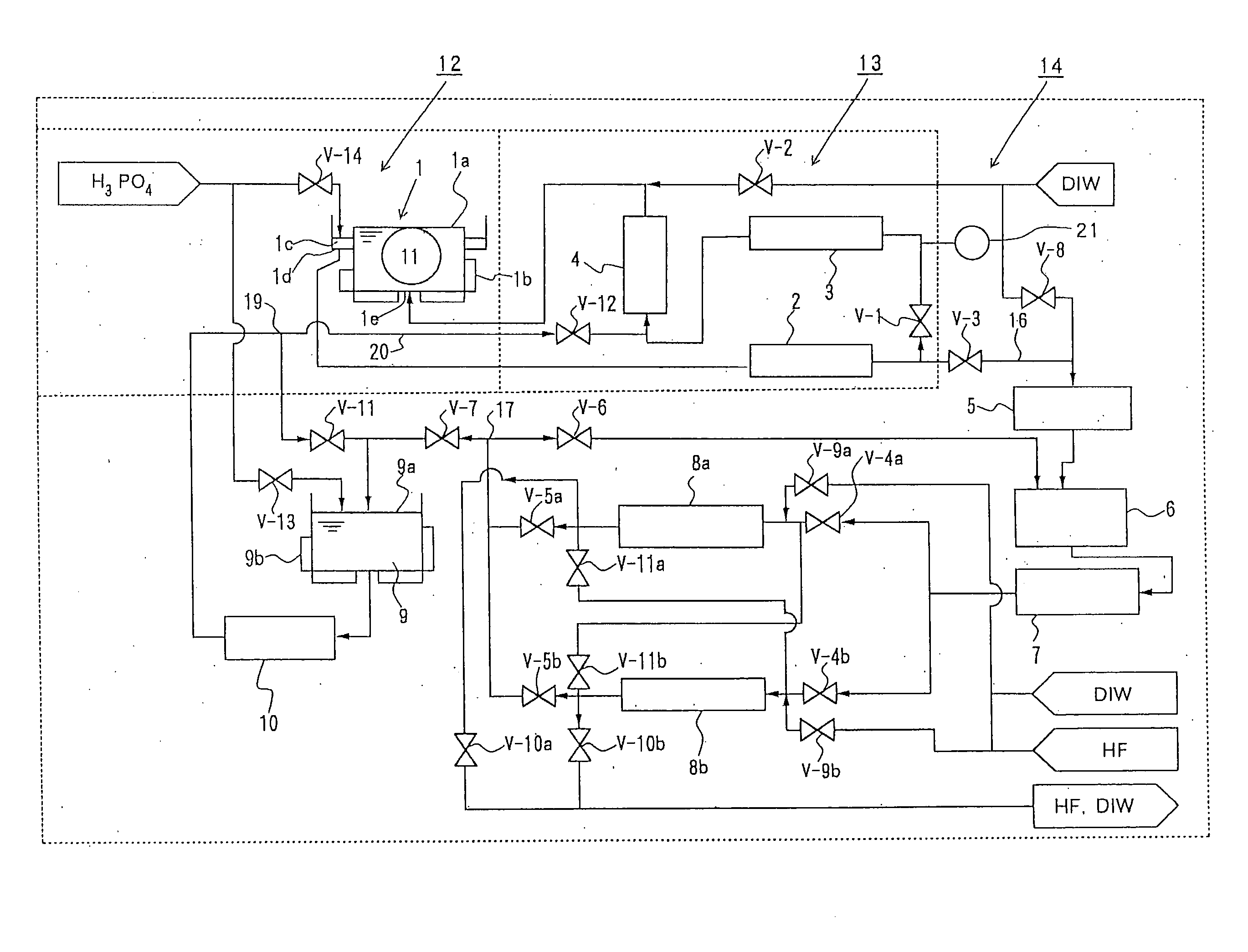
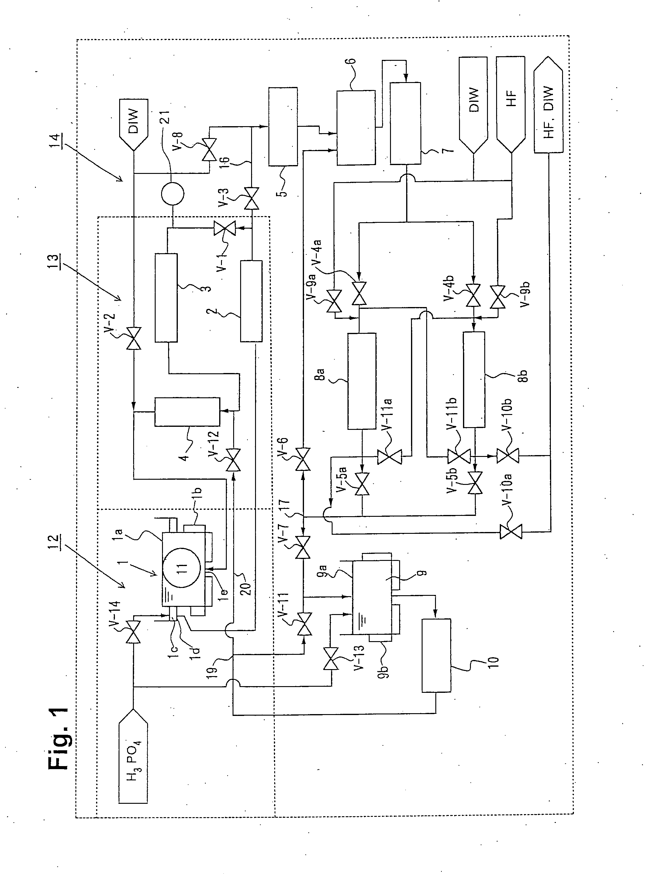
[0034]A silicon oxide film is formed on the surface of the semiconductor wafers as an element separation film. In the formation process, silicon oxide film and silicon nitride film exist on the wafer surface, and for selective etching of the silicon nitride film, phosphoric acid aqueous solution with a concentration at 85-90 mass % is applied as etching solution. During etching the silicon nitride film with said phosphoric acid aqueous solution, silicon component in the silicon nitride film leaks out into phosphoric acid aqueous solution, forming silicon compounds, which accumulate gradually in the phosphoric acid aqueous solution. Namely, this etching process with phosphoric acid attempts at etching silicon nitride film only, leaving silicon oxide film un-etched. However, silicon oxide film is also etched, though slightly. If silicon leaks out into phosphoric acid, the silicon acts as inhibitor to the etching of ox...

example 2

[0036]In Example 2, only the switching time of the filters 8a and 8b was changed as shown in FIG. 4, and all other conditions have remained the same as Example 1, the results of which are given in Table 2 and FIG. 5. As a result, except the case of the first parallel connection of said multiple filters at the operation start, said extracted etching solution was able to be supplied to at least one of filters with an element of a high silicon removal rate of silicon compounds with already deposited silicon compounds, and thus the silicon removal rate in the phosphoric acid regeneration section was able to be maintained constantly at high, as with the case of Example 1.

TABLE 2Si Conc. InSi RemovalFilter ServiceTimeWaferTKrateRouteHr.—ppmmg / min—1.7loaded7688a only5no73.33446188a only10no78.13727268b -> 8a15loaded78.36184268b -> 8a20loaded78.5864268b only25loaded78.81096268a -> 8b30loaded79.90886268a only35loaded76.62512268b -> 8a40loaded76.84969268b -> 8a

example 3

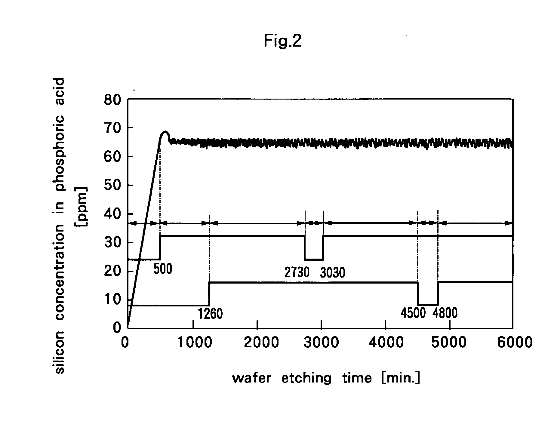
[0037]The time duration when the filters 8a and 8b are connected in series is preferably determined so that the switching should be made at a shorter cycle than a half of the silicon accumulation amount which leads to the filter clogging, since, from FIG. 2 and FIG. 4, each filter is used, at maximum, at two times for silicon accumulation and one time for cleaning. Whereas, if the time is too short, the silicon accumulation amount to the filters becomes insufficient, and silicon compounds do not accumulate in the filters till the silicon removal rate reaches high enough, and therefore the use beyond a certain degree becomes necessary. The maximum silicon accumulation amount till the filter clogging is found to be 29 grams to 43 grams as shown in FIG. 6. Therefore, switching from the series connection to the parallel connection of the filter 8a and the filter 8b should be desirably made at the point that the silicon accumulation amount in the filter reaches 14.5 grams to 21.5 grams. ...


PUM

PropertyMeasurementUnit
timeaaaaaaaaaa
timeaaaaaaaaaa
timeaaaaaaaaaa

Abstract

The present invention provides a regeneration process of the etching solution for the silicon nitride film, applying phosphoric acid aqueous solution, wherein multiple numbers of filters are connected to the piping path of etching solution extracted from the etching tank by switching alternately in parallel or in series; in both cases that said multiple numbers of filters are connected in parallel or in series, said extracted etching solution being supplied to a filter with a filter element of a high silicon removal rate of silicon compounds with already deposited silicon compounds, thus maintaining a high silicon removal rate of silicon compounds.

Description

BACKGROUND OF THE INVENTION[0001]1. Field of the Invention[0002]The present invention relates to a regenerating method of etching solution (phosphoric acid aqueous solution) used for etching a silicon nitride film, an etching method and an etching system, in particular, relating to a technology to eliminate always effectively silicon compounds (a reactive product of silicon nitride with phosphoric acid) contained in an etching solution by etching treatment.[0003]2. Description of the Related Art[0004]In the etching treatment for mass-production lines including those for various substrates, etching is continuously carried out while etching solution is being filter-circulated to remove foreign materials such as debris to keep the etching solution in the tank clean. Such operation is similarly applied to the etching treatment of a silicon nitride film by heated phosphoric acid aqueous solution (etching solution), wherein etching solution is subject to filter-circulation to eliminate si...

Claims


Application Information

Patent Timeline
Patent Type & Authority Applications(United States)
IPC IPC(8): H01L21/306B01D37/00
CPCC09K13/04H01L21/3063
Inventor IZUTA, NOBUHIKOWATATSU, HARURU
Owner APPRECIA TECH
Why Eureka
Try Eureka