Subminiature imaging optical system

a sub-miniature and optical system technology, applied in optics, instruments, lenses, etc., can solve the problems of restricting a degree of freedom in design and destroying optical capabilities, and achieve excellent capacity, high resolution, and effective correction

Inactive Publication Date: 2008-04-17
SAMSUNG ELECTRO MECHANICS CO LTD
View PDF1 Cites 19 Cited by
  • Summary
  • Abstract
  • Description
  • Claims
  • Application Information

AI Technical Summary

Benefits of technology

[0025]The second lens may have a positive refractive power.
[0026]The present invention provides a subminiature imaging optical system capable of effectively correcting various aberrations such as chromatic aberration, distortion, astigmatism, spherical aberration and field curvature, with two lenses each made up of three lens parts.
[0027]In addition, the present invention also provides an optical system which is ultra-miniaturized and has high resolution, while having only two sheets of lenses.
[0028]Further, the present invention also provides a subminiature imaging optical system with excellent capacity, which facilitates mass production since a replica method can be employed.

Problems solved by technology

In order to satisfy miniaturization and low cost, the imaging optical system mounted on a small device such as a mobile phone needs to have a small number of lenses as possible, but this restricts a degree of freedom in designing and undermines the optical capabilities.

Method used


Image

  • Subminiature imaging optical system
  • Subminiature imaging optical system
  • Subminiature imaging optical system

Examples


first embodiment

[0078]Table 1 below shows numerical values according to the first embodiment of the present invention.

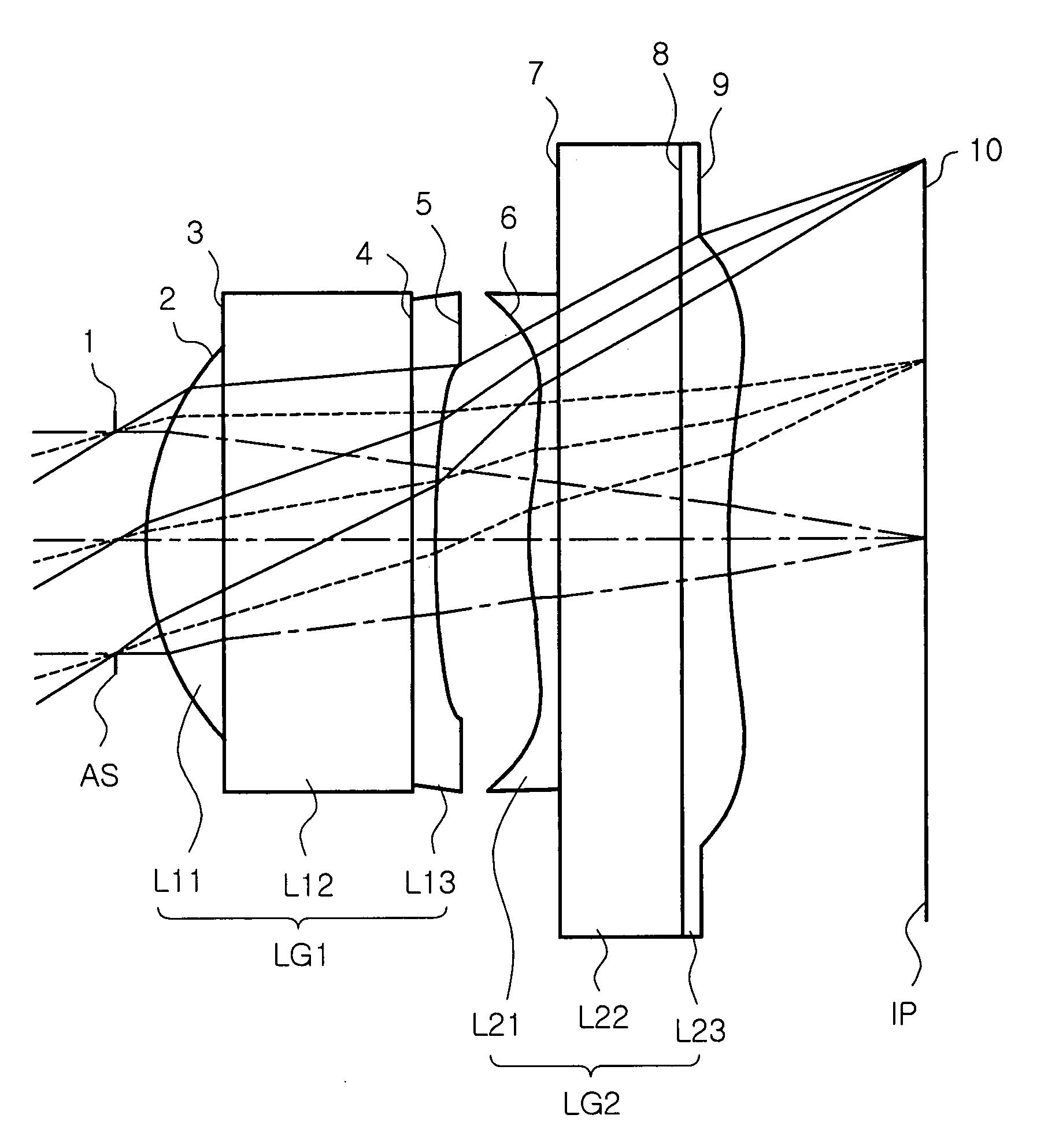
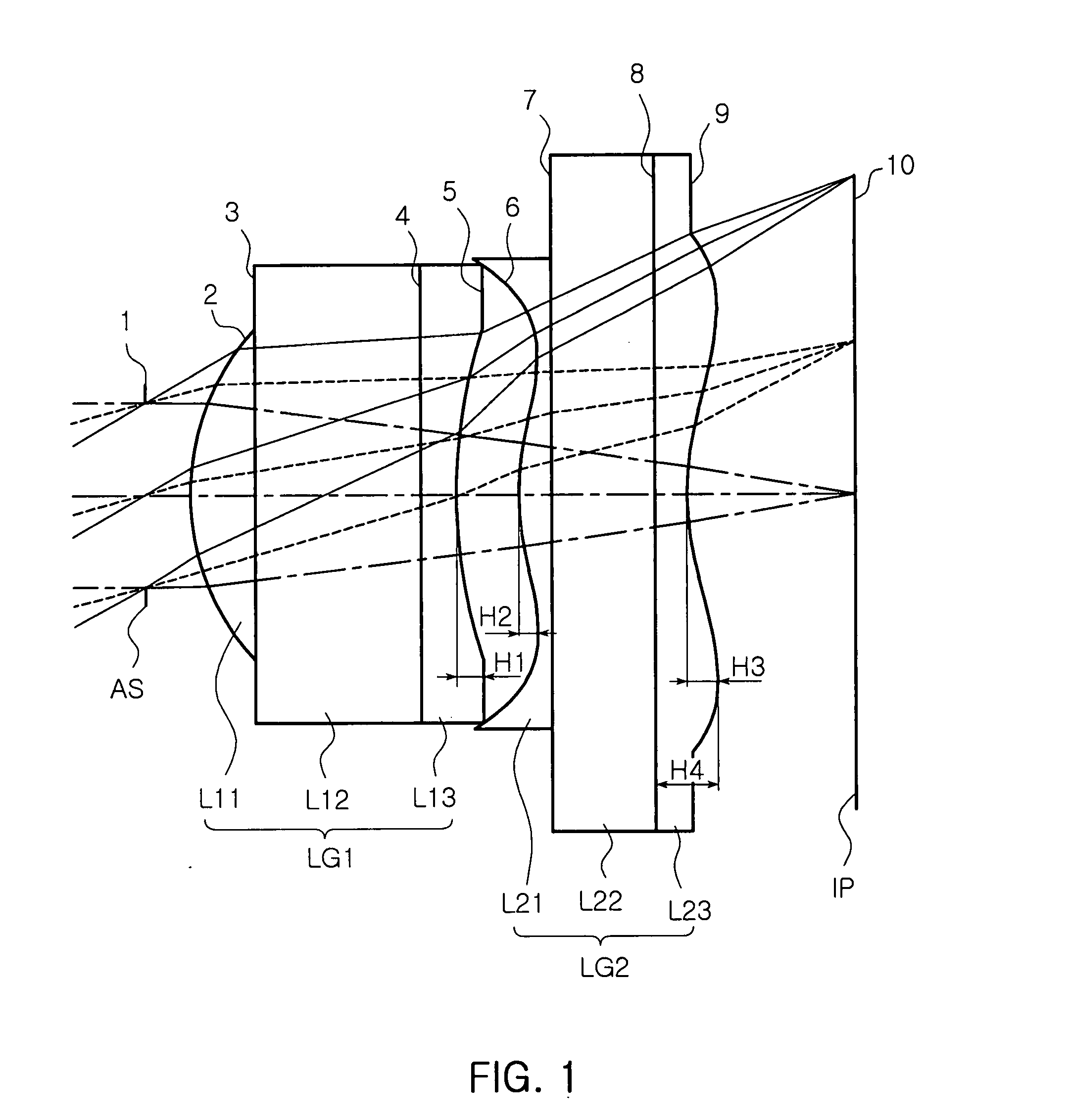
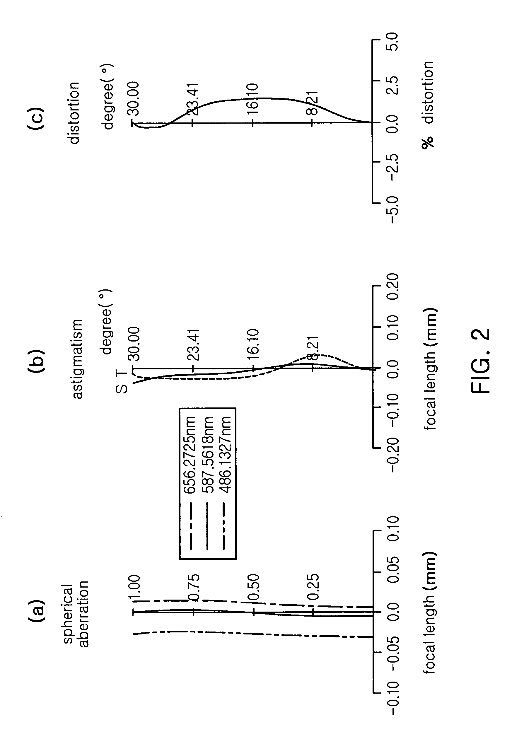
[0079]FIG. 1 is a view of a lens arrangement of the subminiature image forming optical system according to the first embodiment of the present invention, and FIG. 2 shows aberrations of the first embodiment shown in FIG. 1, in which (a) is spherical aberration, (b) is astigmatism and (c) is distortion. In the following diagrams showing astigmatism, “S” represents sagital and “T” represents tangential.

[0080]In the first embodiment, the angle of view is 60 degrees, the distance from an aperture stop surface 1 to the image plane 10 is 2.73 mm, the effective focal length f of the optical system is 2.073 mm, the focal length f1 of the first lens LG1 is 3.5 mm, and the focal length f2 of the second lens LG2 is 4.227. In addition, the largest sag value H1 of the third lens part L13 is 94 μm, the smallest sag value H2 of the fourth lens part L21 is −74 μm, the sag value within the effective...

second embodiment

[0084]Table 3 shows numerical values according to the second embodiment of the present invention.

[0085]FIG. 3 is a view of a lens arrangement of the subminiature according to the second embodiment of the present invention, and FIG. 4 shows the aberrations of the second embodiment shown in FIG. 3, in which (a) is spherical aberration, (b) is astigmatism and (c) is distortion.

[0086]In the second embodiment, the angle of view is 60 degrees, the distance from the aperture stop surface 1 to the image plane is 2.6 mm, the effective focal length f of the optical system is 2.019 mm, the focal length f1 of the first lens LG1 is 2.63 mm, the focal length f2 of the second lens LG2 is 7.14. In addition, the largest sag value H1 of the third lens part L13 is 80 μm, the smallest sag value H2 of the fourth lens part L21 is −30 μm, the sag value within the effective aperture of the fourth lens part L21 is 19 μm, and the largest sag value H3 of the sixth lens part L23 is 50 μm.

[0087]The unit for the...

third embodiment

[0090]Table 5 below shows numerical values according to the third embodiment of the present invention.

[0091]FIG. 5 is a view of a lens arrangement of the subminiature image forming optical system according to the third embodiment of the present invention, and FIG. 6 shows the aberrations of the third embodiment shown in FIG. 5, in which (a) is spherical aberration, (b) is astigmatism and (c) is distortion.

[0092]In the third embodiment, the angle of view is 60 degrees, the distance from the aperture stop surface 1 to the image plane 10 is 2.77 mm, the effective focal length f of the optical system is 2.084 mm, the focal length f1 of the first lens LG1 is 2.761 mm, and the focal length f2 of the second lens LG2 is 13.229 mm. In addition, the largest sag value H1 of the third lens part L13 is 30 μm, the smallest sag value H2 of the fourth lens part L21 is −60 μm, the sag value within the effective aperture of the fourth lens part L21 is 3 μm, and the largest sag value H3 of the sixth l...


PUM


Abstract

A subminiature imaging optical system includes a first lens including a first lens part having a convex object-side surface, a second lens part having an object-side surface in contact with an image-side surface of the first lens part, and a third lens part having an object-side surface in contact with an image-side surface of the second lens part and a concave image-side surface, about the optical axis; and a second lens including a fourth lens part having an object-side surface with a convex center and a concave peripheral portion about the optical axis, a fifth lens part having an object-side surface in contact with an image-side surface of the fourth lens part, and a sixth lens part having an object-side surface in contact with an image-side surface of the fifth lens part, and an image-side surface with a concave center and a convex peripheral portion about the optical axis.

Description

CLAIM OF PRIORITY[0001]This application claims the benefit of Korean Patent Application No. 2006-0100151 filed on Oct. 16, 2006, in the Korean Intellectual Property Office, the disclosure of which is incorporated herein by reference.BACKGROUND OF THE INVENTION[0002]1. Field of the Invention[0003]The present invention relates to an imaging optical system, and more particularly, to a subminiature imaging optical system mounted on a mobile communication terminal, personal digital assistant (PDA) and the like or used in a surveillance camera, a digital camera and the like.[0004]2. Description of the Related Art[0005]In general, mobile communication terminals had only functions of basic communication at their incipient stage. However, with increased use, the mobile communication terminals are required to have diversified functions ranging from photographing to image transmission and video communication, continuously evolving in their functions and services. Recently, a new expanded conce...

Claims


Application Information

Patent Timeline
Patent Type & Authority Applications(United States)
IPC IPC(8): G02B13/18
CPCG02B13/003G02B13/18G02B13/006G02B9/04
Inventor OH, HYE RANJEONG, HO SEOPSHIN, DONG IKYOU, HO SIK
Owner SAMSUNG ELECTRO MECHANICS CO LTD
Why Eureka
Try Eureka