Apparatus and method for generating a clock signal

a clock signal and apparatus technology, applied in the direction of generating/distributing signals, pulse techniques, instruments, etc., can solve the problems of difficult phase-aligning of different clock signals in a circuit, long signal paths of varying lengths, and difficult verification and qualification processes, so as to increase the strength of the second clock signal

Active Publication Date: 2008-04-24
MARVELL ISRAEL MISL
View PDF17 Cites 35 Cited by
  • Summary
  • Abstract
  • Description
  • Claims
  • Application Information

AI Technical Summary

Benefits of technology

[0017]An apparatus comprises one or more of the following: means for receiving a first signal pattern, a second signal pattern, and a first clock signal; means for storing a first state of the first signal pattern at a first transition in the first clock signal; means for storing a second state of the second signal pattern at a second transition in the first clock signal; means for generating a second clock signal by selecting the first st

Problems solved by technology

High speed components and increasingly complex circuits have made it difficult to phase-align the different clock signals in a circuit.
However, this design approach typically involves highly sensitive analog and digital desig

Method used


Image

  • Apparatus and method for generating a clock signal
  • Apparatus and method for generating a clock signal
  • Apparatus and method for generating a clock signal

Examples


Embodiment Construction

[0057]The disclosure can be better understood with reference to the following drawings and description. The components in the figures are not necessarily to scale, emphasis instead being placed upon illustrating the principles of the invention. Moreover, in the figures, like reference numerals designate corresponding parts or elements throughout the different views.

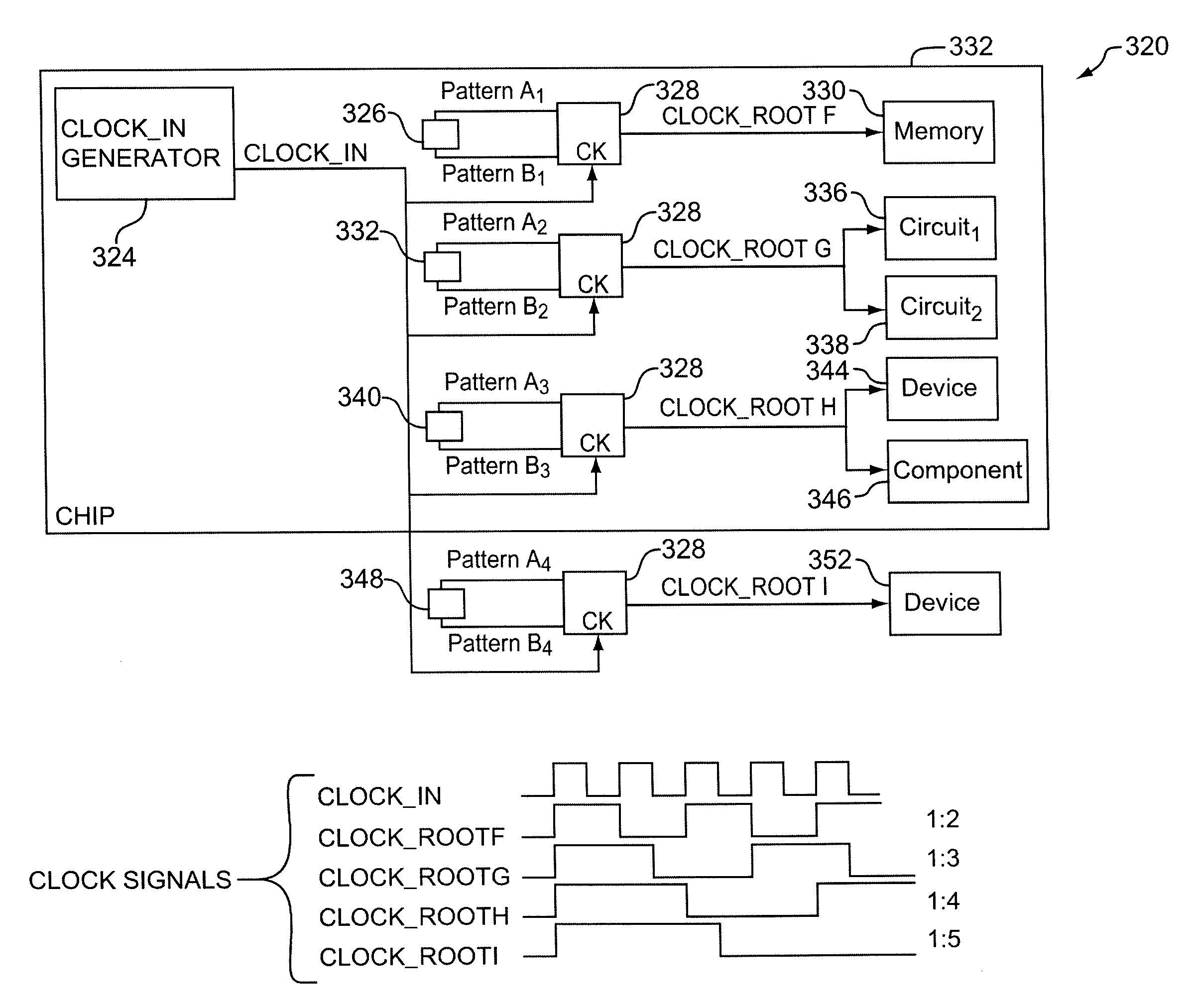
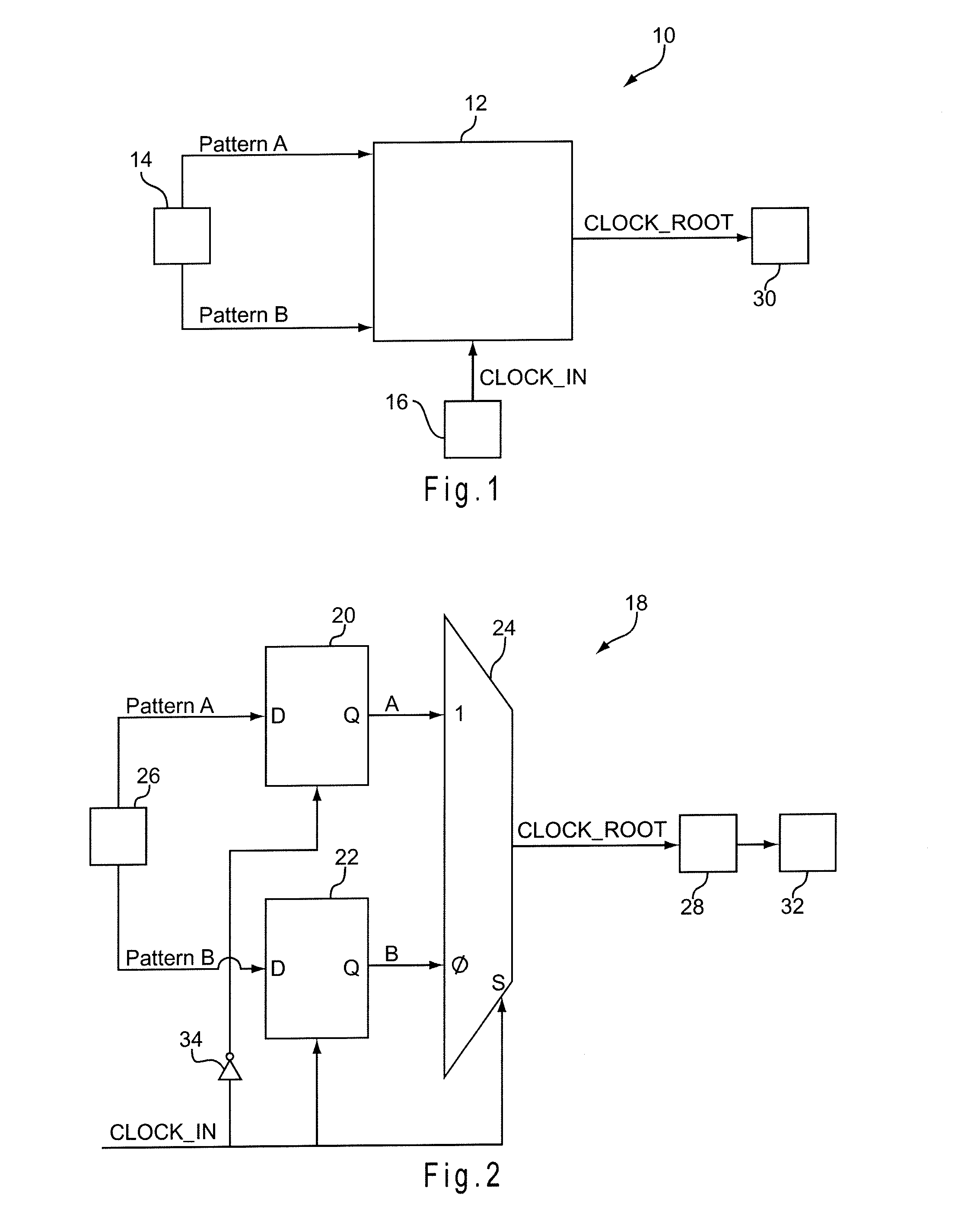
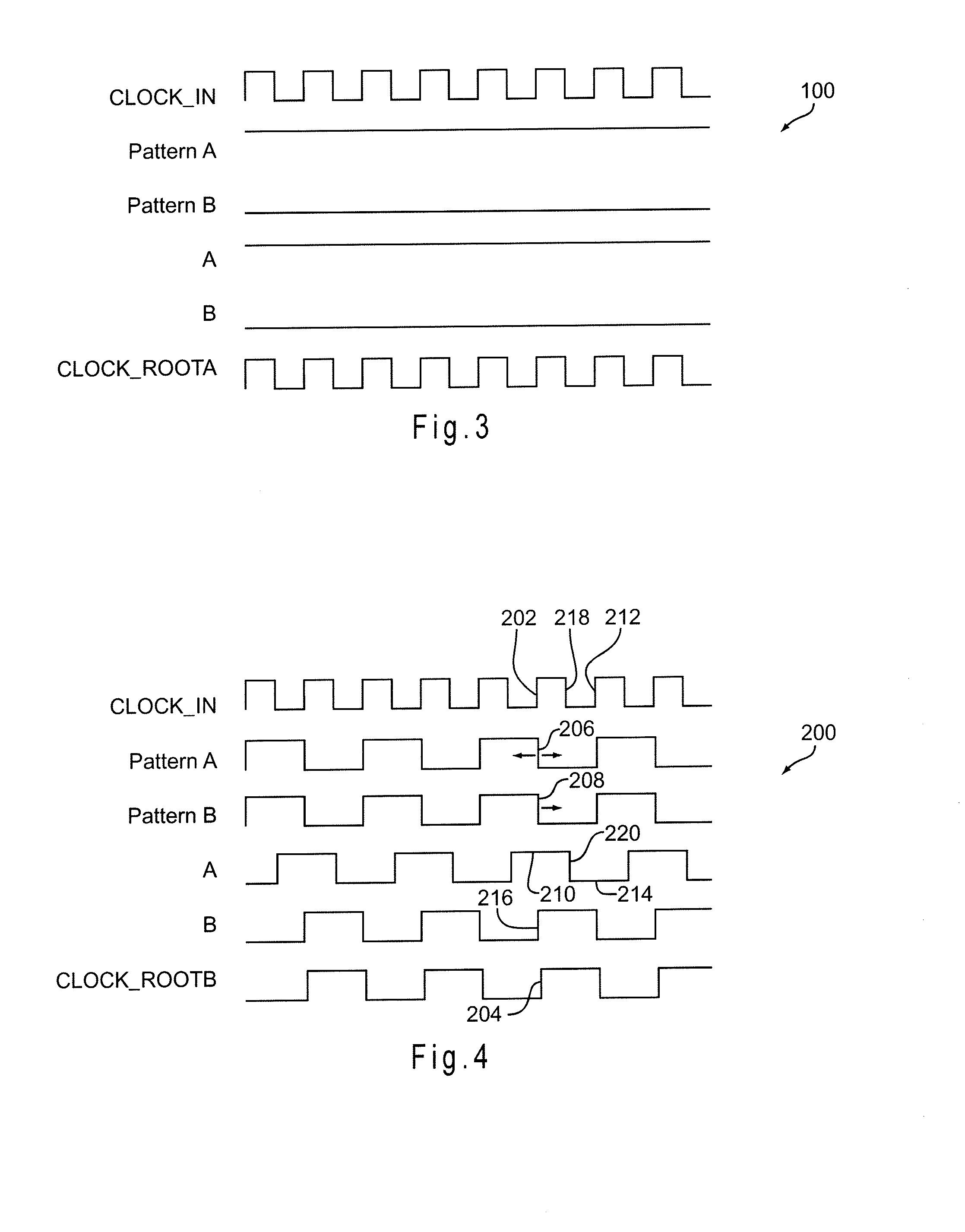
[0058]The embodiments below relate to a clock signal generator having a signal path that is consistent regardless of the ratio of the generated clock signal frequency to a reference clock signal frequency. Thus, substantially identical circuits, all driven by the same reference clock signal (provided by a system reference clock, for example), may be used to generate clock signals of different frequencies and symmetries / asymmetries. For each clock signal generator, the ratio of the generated clock signal frequency to the reference clock signal frequency is controlled by patterns generated by a pattern generator. Different ...


PUM


Abstract

A apparatus and method are disclosed for generating one or more clock signals. A clock signal is generated based on pattern signals and a reference clock signal. When the reference clock signal transitions high, the state of a first pattern signal is output, and when the reference clock signal transitions low, the state of a second pattern signal is output. Successive states of the first and second pattern signals, selected according to the reference clock signal, provide the generated clock signal.

Description

RELATED APPLICATION[0001]This application claims the benefit of U.S. Provisional Application No. 60 / 862,264, filed on Oct. 20, 2006, 60 / 864,688, filed on Nov. 7, 2006, and 60 / 868,825, filed on Dec. 6, 2006, all of which are incorporated herein by reference.COPYRIGHT NOTICE[0002]The appendix of this patent document contains material which is subject to copyright protection. The copyright owner has no objection to the facsimile reproduction by anyone of the patent document or the patent disclosure, as it appears in the Patent and Trademark Office patent file or records, but otherwise reserves all copyright rights whatsoever.BACKGROUND[0003]1. Technical Field[0004]The present disclosure relates to the field of clock signal generation, and more particularly to the generation of multiple phase-aligned clock signals.[0005]2. Related Art[0006]In an ideal synchronous circuit, all data transitions occur simultaneously and all components are synchronized by one or more related clock signals. ...

Claims


Application Information

Patent Timeline
IPC IPC(8): H03L7/06
CPCG06F1/08H03K5/135G11C7/222G11C7/22
Inventor STOLER, GILBOURSTEIN, IDOBANAI, YIFTACH
Owner MARVELL ISRAEL MISL
Why Eureka
Try Eureka