Ultrasonic probe and ultrasonic diagnostic apparatus

a technology of ultrasonic probes and diagnostic equipment, applied in the direction of mechanical vibration separation, instruments, specific gravity measurement, etc., can solve the problems of insufficient mechanical strength of the mesa structure, particularly serious problems relating to defective channels, and ensure a sufficient insulation

Inactive Publication Date: 2008-05-01
KK TOSHIBA
View PDF5 Cites 47 Cited by
  • Summary
  • Abstract
  • Description
  • Claims
  • Application Information

AI Technical Summary

Problems solved by technology

The problem relating to the defective channel is particularly serious when it comes to a two dimensional array probe having a small channel area not larger than 0.1 mm2.
It is possible for this mesa structure to have an insufficient mechanical strength.
Also, where a large amount of fibers, such as carbon fibers or potassium titanate, are contained in a large amount in a resin as disclosed in JP-A 9-127955 (KOKAI) or JP-A 2006-33801 (KOKAI), the electric conductivity of the fiber makes it difficult to ensure a sufficient insulation between the adjacent channels, which gives rise to an inconvenience that a pulse current cannot be applied.
However, the strength and the uniformity in a small area of the backing layer are not considered at all in each of these patent documents.

Method used


Image

  • Ultrasonic probe and ultrasonic diagnostic apparatus
  • Ultrasonic probe and ultrasonic diagnostic apparatus
  • Ultrasonic probe and ultrasonic diagnostic apparatus

Examples


example 1

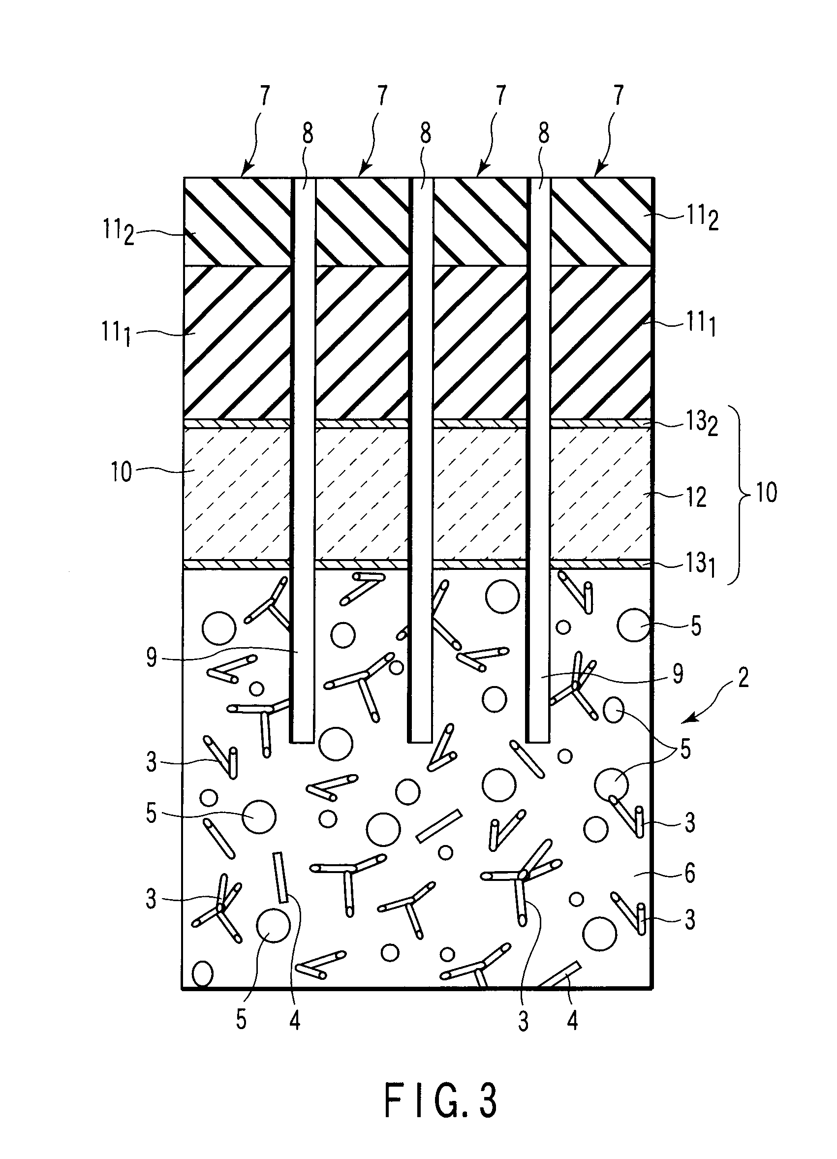
[0084]A plurality of tetrapod-like zinc oxide fibers (TPZ) forming bonded fibers were added to “Ecobond 27”, which is a trade name of a liquid epoxy resin manufactured by Emerson & Coming Inc., hereinafter abbreviated as “EPR”. The zinc oxide fibers (TPZ) were added to the liquid epoxy resin EPR in an amount of 3% by weight based on the sum of the liquid epoxy resin EPR and TPZ, followed by further adding a curing agent to the mixture. Then, the resultant composition was put in a polyethylene cup and stirred and uniformly mixed for 5 minutes by using a rotary mixer, thereby preparing an acoustic backing composition. The PZT used was formed of four zinc oxide fibers bonded to each other at one edge portions and extending in different directions in the other edge portions. Each of the zinc oxide fibers had a diameter of about 2 μm and a length of 40 to 50 μm. Also, the plural bonded fibers (TPZ) included bonded fibers consisting of four zinc oxide fibers having substantially the same ...

examples 2 to 7

[0086]The raw material of the acoustic backing layer was manufactured as in Example 1, except that EPR, TZP and a second filler were mixed in the mixing ratio shown in Table 1.

example 8

[0087]A plurality of tetrapod-like zinc oxide fibers (TPZ) similar to those used in Example 1 were added to a liquid NBR (trade name of a liquid nitrile rubber manufactured by Nippon Zeon Inc., which is hereinafter abbreviated as NBR) in an amount of 5% by volume based on the sum of NBR and TPZ. Then, Fe2O3 particles having an average particle diameter of 5 to 10 μm were added to the mixture in an amount of 5% by volume based on the sum of NBR and the iron oxide particles. The resultant composition was put in a polyethylene cup and stirred for 5 minutes by using a rotary mixer so as to mix uniformly the composition, thereby obtaining an acoustic backing composition. The acoustic backing composition was defoamed for 10 minutes in a vacuum container, followed by putting the defoamed composition in a cup formed of Teflon (registered trademark). Further, the raw material of the acoustic backing layer was manufactured by curing the defoamed composition at 80° C. for 24 hours.


PUM

PropertyMeasurementUnit
lengthaaaaaaaaaa
lengthaaaaaaaaaa
particle diameteraaaaaaaaaa

Abstract

An ultrasonic probe comprises an acoustic backing layer made of a composite resin material including a resin and a plurality of bonded fibers contained the resin, each of the bonded fibers being formed of a plurality of zinc oxide fibers bonded to each other at one edge portions and extending in different directions in the other edge portions, the composite resin material exhibiting an acoustic impedance of 1.3 to 6 MRayls at 25° C., a plurality of channels arranged on the acoustic backing layer with space, each channel having a piezoelectric element and an acoustic matching layer formed on the piezoelectric element, and an acoustic lens formed to cover at least the surface of the acoustic matching layer of each channel.

Description

CROSS-REFERENCE TO RELATED APPLICATIONS[0001]This application is based upon and claims the benefit of priority from prior Japanese Patent Application No. 2006-297115, filed Oct. 31, 2006, the entire contents of which are incorporated herein by reference.BACKGROUND OF THE INVENTION[0002]1. Field of the Invention[0003]The present invention relates to an ultrasonic probe for transmitting ultrasonic signals to, for example, an object and for receiving the ultrasonic signals reflected from the object and also relates to an ultrasonic diagnostic apparatus comprising the ultrasonic probe.[0004]2. Description of the Related Art[0005]An array type ultrasonic probe performing the function of transmitting and receiving ultrasonic signals is used mainly in a medical ultrasonic diagnostic apparatus or an ultrasonic image inspecting apparatus, which transmits an ultrasonic signal to an object and receives the reflected signal (echo signal) coming from within the object for forming an image of the...

Claims


Application Information

Patent Timeline
Patent Type & Authority Applications(United States)
IPC IPC(8): G01N29/00A61B8/00
CPCG10K11/002B06B1/0629
Inventor YAMASHITA, YOHACHIHOSONO, YASUHARU
Owner KK TOSHIBA
Why Eureka
Try Eureka