Device And Method For Detecting Symbol Timing For Highly Bandwidth Efficient High Order Modulation System
a high-order modulation system and symbol timing technology, applied in the direction of synchronising arrangement, digital transmission, electrical equipment, etc., can solve the problems of low bandwidth efficiency, small detection signal gain, and inapplicability of symbol timing synchronization detectors
- Summary
- Abstract
- Description
- Claims
- Application Information
AI Technical Summary
Benefits of technology
Problems solved by technology
Method used
Image
Examples
first embodiment
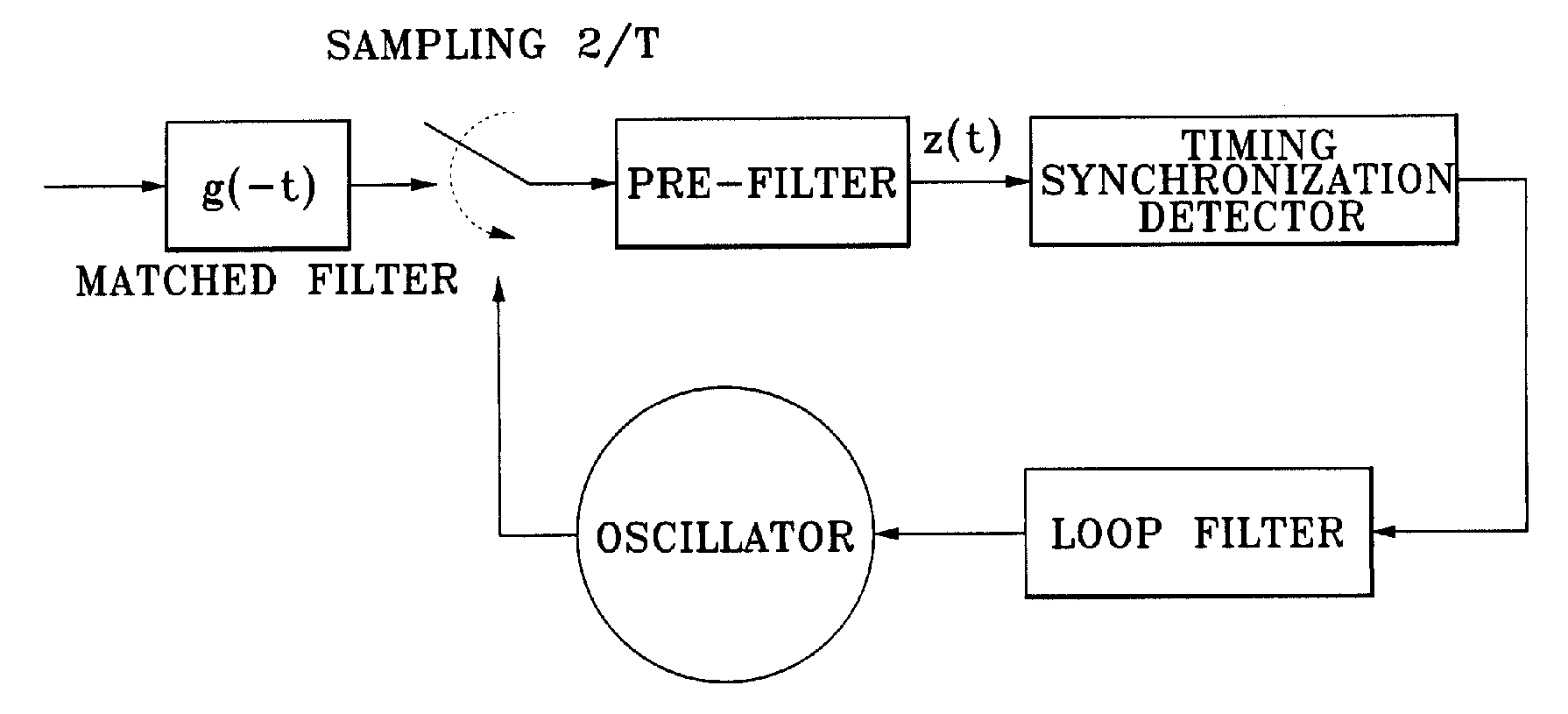
[0056]Below, unew1(T) is a timing synchronization detection algorithm according to the present invention. FIG. 4 illustrates a configuration of the timing synchronization detector as described above.
unew1(τ)=z(τ-3T2)[z(τ)-z(τ-T)+z(τ-2T)-z(τ-3T)]
[0057]In the present invention, it is assumed that the frequency bandwidth is limited, and a signal is a real and even function in time domain. With the above assumptions, a timing synchronization detection curve, i.e., S-curve computed by using Table 2 is given by,
Snew1=[2C1(12)+2C1(32)]sin(2πτT)
[0058]The timing synchronization detector includes a first delay line 111 delaying a received signal z(t) by a half symbol period, a second delay line 112 delaying an output of the first delay line 111 by a half symbol period, a third delay line 113 delaying an output of the second delay line 112 by a half symbol period, a fourth delay line 114 delaying an output of the third delay line 113 by a half symbol period, a fifth delay line 115 delaying an ...
third embodiment
[0076]FIG. 7 illustrates a configuration of a timing synchronization detector according to the present invention, in which a Hilbert transformer is used.
[0077]The timing synchronization detector includes a Hilbert transformer 310 Hilbert transforming a received signal z(τ); and a multiplier 341 multiplying an output of the Hilbert transform 310 and the received signal Z(τ).
fourth embodiment
[0078]FIG. 8 illustrates a configuration of a timing synchronization detector according to the present invention, in which a differentiator is used.
[0079]The timing synchronization detector includes a differentiator 410 differentiating the received signal Z(τ); and a multiplier 441 multiplying an output of the differentiator 410 and the received signal Z(τ).
[0080]In this case, a half symbol and a quarter symbol delay is applicable. Also, pre-filters 305 and 405 may be included to remove noise from a received signal.
[0081]Table 4 below shows an algorithm and detector curve of a timing synchronization detector using a Hilbert transform and differentiation.
[0082]Table 4 Algorithm and S-curve in the case of applying Hilbert transform and differentiation
Algorithmz(t)=∑-∞∞akh(t-kT)+n(t)S-curveHilbert transformu(τ)=z(τ){z^(τ)},wherez^(t)=1πt⊗z(t)Htransform(f)=-jf>0=0f=0=+jf0 SHilbert=+2[1T∫01TH(1T-v)H(v)dv]sin2πτT=+2D1sin2πτT Differentiationu(τ)=z(τ){ddτZ(τ)}SDiff=-2[2πT∫01TH(1T-v)H(v)vdv]...
PUM
 Abstract
Description
Claims
Application Information
 - R&D
- Intellectual Property
- Life Sciences
- Materials
- Tech Scout
- Unparalleled Data Quality
- Higher Quality Content
- 60% Fewer Hallucinations
Browse by: Latest US Patents, China's latest patents, Technical Efficacy Thesaurus, Application Domain, Technology Topic, Popular Technical Reports.
© 2025 PatSnap. All rights reserved.Legal|Privacy policy|Modern Slavery Act Transparency Statement|Sitemap|About US| Contact US: help@patsnap.com


