
Spray development of photosensitive plates

a technology of photosensitive plates and spraying, which is applied in the direction of lithography, photosensitive materials, instruments, etc., can solve the problems of difficult to ensure the clean up of shadows and background areas without attacking highlight dots, and difficult to get uniform development or consistent development, etc., to achieve excellent development

Inactive Publication Date: 2008-05-01
ANOCOIL
View PDF6 Cites 12 Cited by
  • Summary
  • Abstract
  • Description
  • Claims
  • Application Information

AI Technical Summary

Benefits of technology

[0003]We have discovered that excellent development can be achieved by covering the coating with a turbulent flow of fresh developer solution.
[0006]In one method embodiment, an imaged plate is developed using a pressurized spray to apply the developer. The developer solution need only be sufficiently alkaline to enable the fluid to penetrate the coating. Consequently, the alkaline developer composition sufficient to give excellent results can be simply water with approximately 5% sodium metasilicate, applied at ambient temperature. The resultant developed plate has excellent uniform development. The background and shadows clean out thoroughly and the highlight dots are retained. The spray is preferably applied by a single spray bar with overlapping nozzle flow. Thus the processor length can be significantly shortened. Useful spray pressures are in the range of about 5 to about 250 psi. When this technique is used at high spray pressure, the development can be enhanced by the mechanical force of the impinging spray.
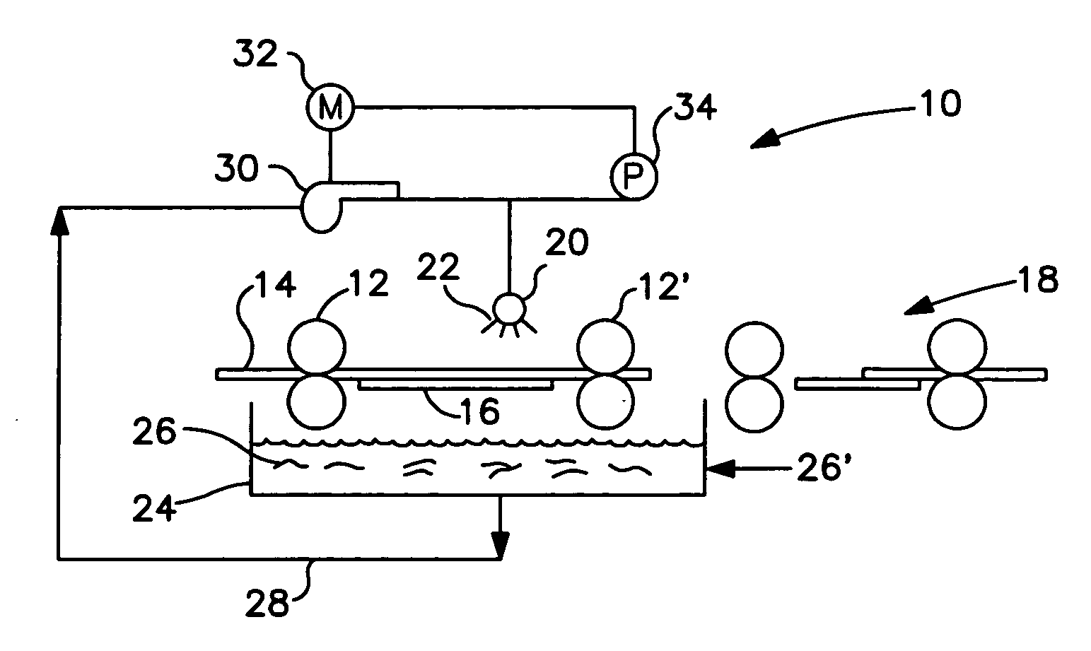
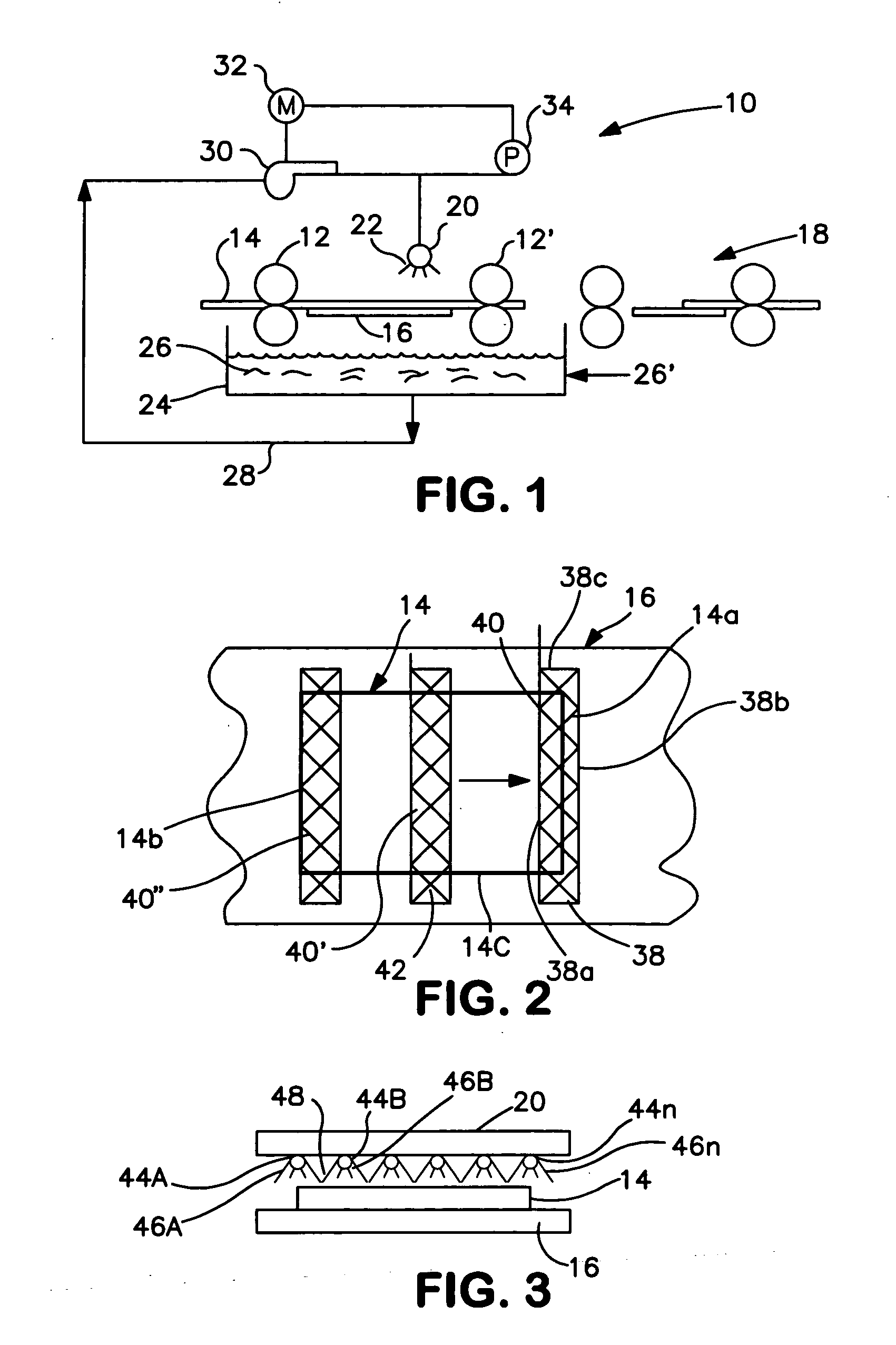
[0008]Another embodiment is directed to a system for developing a planographic printing plate having an imaged photosensitive coating on a substrate. The system comprises a flat support surface and a feeder for delivering plates in series to the support surface. A nozzle array is spaced from the support surface and oriented to discharge alkaline developer solution transversely onto a plate when on the support surface. A closed source vessel contains fresh alkaline developer solution, and a supply line delivers developer solution from the source vessel to the nozzle array. A pump or the like pressurizes the developer from the supply line, to the nozzle array, whereby a pressurized flow of developer solution can be selectively directed as a flow pattern transversely at the entire, but preferably a portion, e.g., up to about 25%, of the total surface area of the plate. At least one of the support surface or nozzle array is movable at a constant speed relative to the other, such that successive target areas of the plate are dynamically flooded with fresh developer solution until the plate is fully developed. Developer overflow is preferably recycled, and a replenishment flow of developer chemical can compensate for drag out and any other diminution of recycled developer effectiveness.
[0009]It can be appreciated that with the present invention, a unit area of coating is in contact with fresh developer continuously for a short but known local dwell time, and that all such unit areas on the same plate and for all subsequently developed plates experience at least a prescribed minimum dynamic development condition. Rather than achieving uniformity of development conditions by applying a known quantity of developer solution on a unit area of the plate and maintaining quiescence during a long and slow conveyance while that same quantity of developer percolates through the soluble regions, the present invention relies on the antithesis of quiescence, i.e., turbulent contact with fresh developer over a short dwell time.
[0010]An advantage arising from the range of conditions that yields acceptable developed plates, is that optimization can be achieved by mechanical adjustment or control, rather than by chemistry or temperature control. This is far easier, especially in commercial end-user operations where laboratory exactitude cannot be expected. Furthermore, a variety of plate types and sizes can be accommodated by easy adjustments to a universal developer station, such as discharge pressure, number of nozzles required to span the plate width, transport speed, and developer solution. Because only fresh developer is continuously contacting all the coating for substantially the same dwell time, without interference by a boundary layer, localized currents, or non-uniform rates of diffusion through the coating, increasing the plate size does not increase the variability of the development from one corner or edge of the plate to the opposite corner or edge.

Problems solved by technology

This presents difficulties to get uniform development or consistent development from plate to plate.
It is also difficult to assure that shadows and background areas clean out without attacking highlight dots in halftones.

Method used


Image

  • Spray development of photosensitive plates
  • Spray development of photosensitive plates

Examples


example 1

)

[0030]An unexposed plate was processed using the modified PROTECK XPH spray development apparatus. The developer solution was 5% sodium metasilicate (SMS), the plate dwell time was 5 seconds and the spray pressure was 70 psi. This plate exhibited a 0% loss of coating.

example 2

)

[0031]An unexposed plate was processed in the same manner as in Example 1 except that the plate dwell time was increased to 20 seconds. This plate exhibited a 23% loss of coating.

example 3

)

[0032]An unexposed plate was processed in a standard immersion type processor, model MX-33 available from CA Systems, Fort Atkinson, Wis. The developer was T-8 Thermal developer commercially available from Anocoil Corporation, which is formulated for use in this type of processor. The plate dwell time was 20 seconds in the sump of developer. This plate exhibited a 10% loss of coating.


PUM

PropertyMeasurementUnit
pressuresaaaaaaaaaa
volumeaaaaaaaaaa
forward angleaaaaaaaaaa

Abstract

Excellent development of photosensitive coatings on planographic printing plates is achieved by directing a dynamic flow of fresh alkaline developer solution that impinges on a target area of the coating extending the width of the plate and floods the target area with a turbulent flow. At sufficient volumetric flow rate, the developer solution at the target area is constantly displaced during the development time, whereby no boundary layer forms on and travels with the plate during the development time and thus the target area is always in contact with fresh developer solution.

Description

BACKGROUND OF THE INVENTION [0001]The present invention relates to the development of planographic printing plates, and especially lithographic printing plates having an imaged photosensitive coating with regions that are soluble in an alkaline developer solution.[0002]Historically, the processing of positive plates involves immersion of the plate in a sump of developer as it passes through a plate processor. The plate then exits the sump, and is typically subjected to a rotating brush or molleton and a nip roll set prior to being rinsed. This method of development relies entirely on the chemical dissolution of the solubilized coating to produce the plate. The developer is an alkaline solution typically containing an alkali metal silicate and / or alkali metal hydroxide along with other wetting agent / surfactants. The temperature of the developer is critical, and must be controlled over a small range. The development is influenced by any flow dynamics (e.g. even small eddy currents) in...

Claims


Application Information

Patent Timeline
Patent Type & Authority Applications(United States)
IPC IPC(8): G03D5/00
CPCB41C1/1008G03D5/00G03F7/3042B41C2210/262B41C2210/04B41C2210/06B41C2210/24B41C2210/02
Inventor FROMSON, HOWARD A.ROZELL, WILLIAM J.RYAN, WILLIAM J.
Owner ANOCOIL
Learn More