
Nut plate fastener assembly for hard metal materials

a technology of hard metal materials and fasteners, which is applied in the direction of fastening means, fastener tools, screws, etc., can solve the problems of not being able to achieve the mechanical properties required, affecting the performance of the workpiece, and not being able to achieve the proper shear load transfer. achieve the effect of not risking the delamination of the workpi

Inactive Publication Date: 2008-05-01
SPS TECH LLC
View PDF97 Cites 6 Cited by
  • Summary
  • Abstract
  • Description
  • Claims
  • Application Information

AI Technical Summary

Benefits of technology

[0016] An object of an embodiment of the present invention is to provide a rivetless nut plate assembly which can be installed into an aperture of a composite material workpiece without risking delamination of the workpiece.
[0017] Another object of an embodiment of the present invention aims to fasten a rivetless nut plate to a composite structure without the use of bonding agents, additional holes or satellite rivets, and without damaging the structure.
[0018] Another object of an embodiment of the present invention is to provide a rivetless nut plate assembly which can be installed into an aperture of a hard metal structure without requiring the formation of additional holes in the structure to precise tolerances.
[0020] Briefly, and in accordance with the foregoing, an embodiment of the present invention provides a rivetless nut plate assembly, which is fully preassembled, which can be installed into an aperture of a composite material workpiece, such as a carbon fiber structure, without risking delamination of the workpiece. The rivetless nut plate assembly includes a nut, a holding bracket, a retainer, and a sleeve member. Additionally, a stem is used to install the rivetless nut plate assembly. The sleeve member is configured such that the nut plate assembly can be installed in a composite material workpiece without risk of delamination. The sleeve member may be formed of 45Cb-55Ti Titanium Columbium, as Titanium Columbium is a high strength and ductile material that resists corrosion in the presence of, for example, a carbon fiber composite structure. Monel, Titanium alloys, and other soft Nickel alloys are also good material selections for the sleeve, for similar reasons. Non-metallic materials with high tensile and shear strengths, such as Torlon or Parmax, would provide the desired corrosion protection and also offer a potential weight savings.

Problems solved by technology

Unfortunately, with composite structures, the introduction of holes in the material and subsequently fasteners in those holes, create unique problems not existing with most aerospace structural materials.
Due to the properties of composites, too much radial expansion of the work hole caused by the fastener sleeve leads to delamination of the composite, while too little radial expansion hampers proper shear load transfer.
Also unfortunately, with hard metal structures having a hardness of at least 25 Rc, such as Titanium and Steel alloys, the radial expansion of the fastener sleeve does not allow for any embedding process to take place and, thus, does not achieve the required mechanical properties.
Due to the nature of composite material, each drilled hole, as well as each additional installed fastener, endangers the integrity of the structure.
Performing the drilling process in the composite material is difficult and costly, and can also damage the structure by exposing fibers to water absorption problems, while each installed fastener can damage the composite structure due to overfill conditions.
In overfill conditions, the excessive radial expansion of the fastener can lead to delamination of the composite structure.
Finally, the integrity of the bonding process is not easily verifiable and it can deteriorate due to environmental changes such as heat, moisture and chemicals.
The main disadvantage of the outdated riveted nut plate method is that it is time intensive.

Method used


Image

  • Nut plate fastener assembly for hard metal materials
  • Nut plate fastener assembly for hard metal materials
  • Nut plate fastener assembly for hard metal materials

Examples


Embodiment Construction

[0054] While this invention may be susceptible to embodiment in different forms, there are shown in the drawings and will be described herein in detail, specific embodiments with the understanding that the present disclosure is to be considered an exemplification of the principles of the invention, and is not intended to limit the invention to that as illustrated.

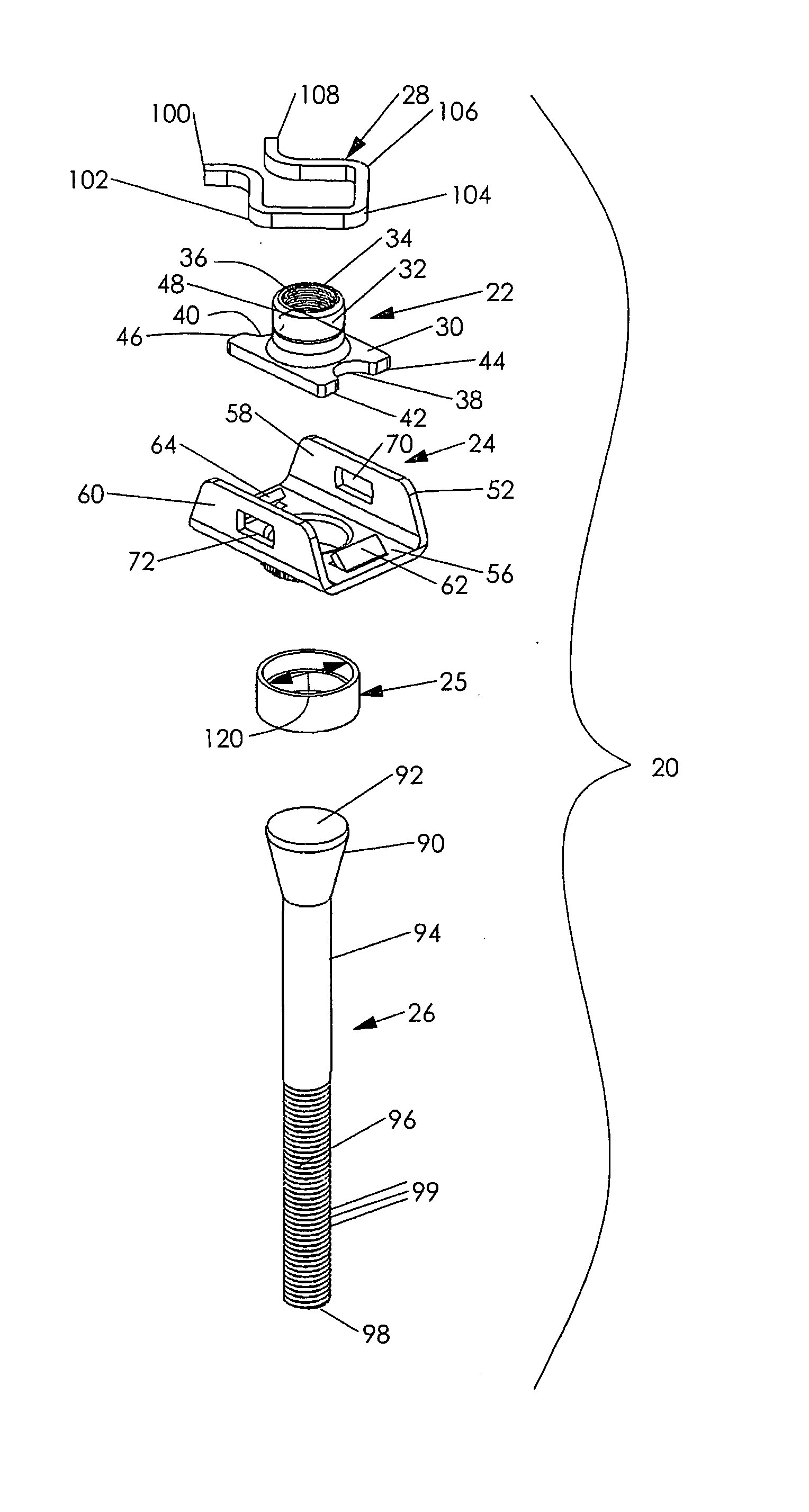
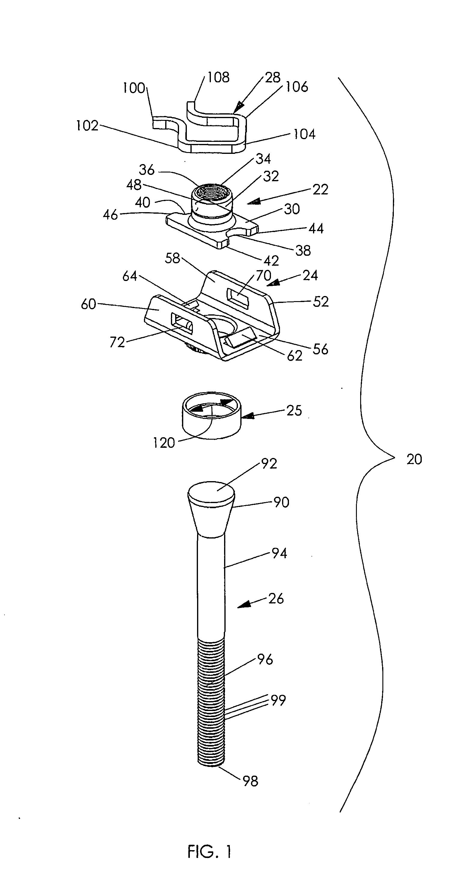
[0055]FIG. 1 is an exploded perspective view of a rivetless nut plate assembly 20 which is in accordance with an embodiment of the present invention. The rivetless nut plate assembly 20 is configured such that it can be installed into an aperture of a composite material workpiece without risking delamination of the workpiece, and can be installed without having to use bonding agents, additional holes or satellite rivets.

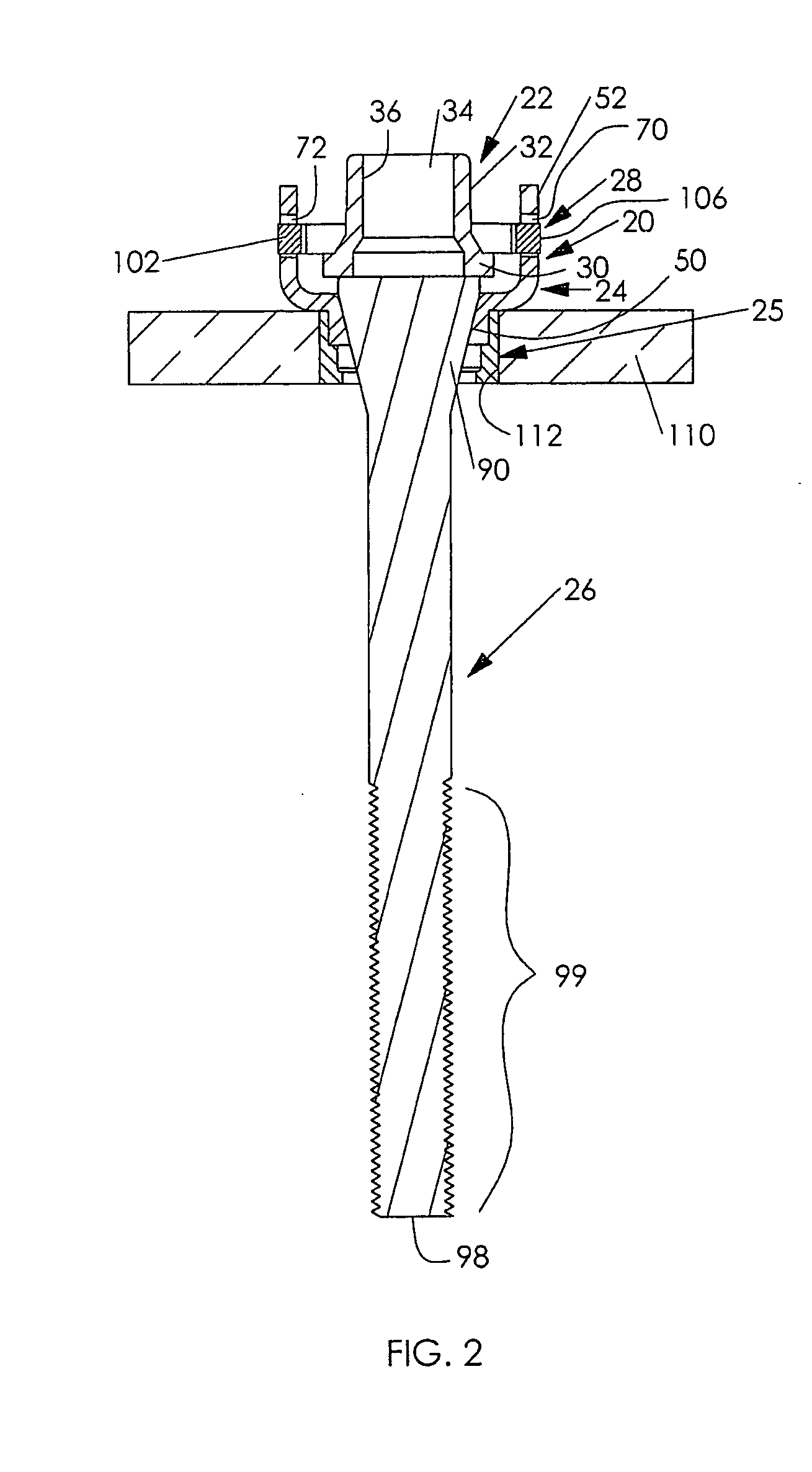
[0056] The nut plate assembly 20 includes a nut 22, a holding bracket 24, a sleeve 25 and a retainer 28. Additionally, before installation, the nut plate assembly 20 includes a stem 26 that is used to inst...


PUM


Abstract

A rivetless nut plate assembly, which is fully preassembled, which can be installed into an aperture of a hard metal material workpiece having a hardness of at least 25 Rc, such as Titanium and Steel Alloys. The rivetless nut plate assembly includes a nut, a holding bracket, a retainer, and a sleeve member. Additionally, a stem is used to install the rivetless nut plate assembly. The sleeve member is configured such that the nut plate assembly can be installed in a hard metal material workpiece. The sleeve member may be formed of a high strength, but ductile material, such as Titanium Columbium, Monel, soft Nickel alloys or soft Titanium alloys.

Description

RELATED APPLICATION Priority Claim [0001] This application is a continuation-in-part of U.S. patent application Ser. No. 11 / 874,347, filed Oct. 18, 2007, and entitled “Nut Plate Fastener Assembly For Composite Materials”. U.S. patent application Ser. No. 11 / 874,347, in turn, claims the benefit of U.S. Provisional Application Ser. No. 60 / 863,828, filed Nov. 1, 2006, and entitled “Nut Plate Fastener Assembly For Composite Materials”. U.S. patent application Ser. No. 11 / 874,347 and U.S. Provisional Patent Application No. 60 / 863,828 are hereby incorporated herein by reference in their entireties.BACKGROUND OF THE INVENTION [0002] The present invention generally relates to nut plate fastener assemblies, and more specifically relates to a rivetless nut plate fastener assembly which is configured for use with a composite material workpiece and a rivetless nut plate fastener assembly which is configured for use with a hard metal material workpiece. [0003] Fasteners are used in the aerospace...

Claims


Application Information

Patent Timeline
Patent Type & Authority Applications(United States)
IPC IPC(8): F16B37/04
CPCF16B17/006Y10S411/969F16B37/062F16B37/045
Inventor TOOSKY, RAHMATOLLAH FAKHRIESHRAGHI, SOHEIL
Owner SPS TECH LLC
Learn More