These heavy gearboxes, which are mounted atop high towers, often located in remote locations such as on a mountain or offshore, experience severe fluctuations in wind conditions and temperature and are often exposed to a corrosive
seawater environment and / or
abrasive particulates.
A gearbox failure can require removing the gearbox using mammoth equipment, and rebuilding it back at the manufacturer's facility followed by reinstallation at the remote location.
The concurrent loss of electrical generation is also a costly event unto itself.
Firstly, this will reduce the amount of
metal-to-
metal contact which produces
lubricant debris and which is known to be destructive to gears and bearings.
Honing could have been a consideration for wind turbine gearboxes; except that it is cost prohibitive on such large gears as most
honing equipment is limited to
processing gears having a
diameter of 12 inches or less.
Thus, the
lubricant film can be penetrated by peak asperities, and metal-to-metal contact generates
metal debris from the gear teeth.
However, a major source of wind turbine gear box failure is failure of the bearings.
Even with run-in achieving the above finishes, metal to metal teeth contact continues on the planetary gear stage teeth and produces lubricant debris, which in turn contributes to the rapid bearing failures.
In contrast, chemically accelerated vibratory
superfinishing to a condition of Ra<0.3 micron was thought to be too smooth for large wind turbine generators in that the teeth flanks would have insufficient lubricant retention for operation and tooth failure was predicted.
Thus, it was questionable whether or not
superfinishing using chemically accelerated vibratory finishing of the input planetary stage would add any performance value to the gear box.
Only lengthy and costly field testing could provide the answer.
In addition, it was thought by those skilled-in-the-art that the large, heavy gears that make up an input planetary stage of a large wind turbine generator could not be processed in vibratory finishing equipment used in the chemically accelerated vibratory finishing process.
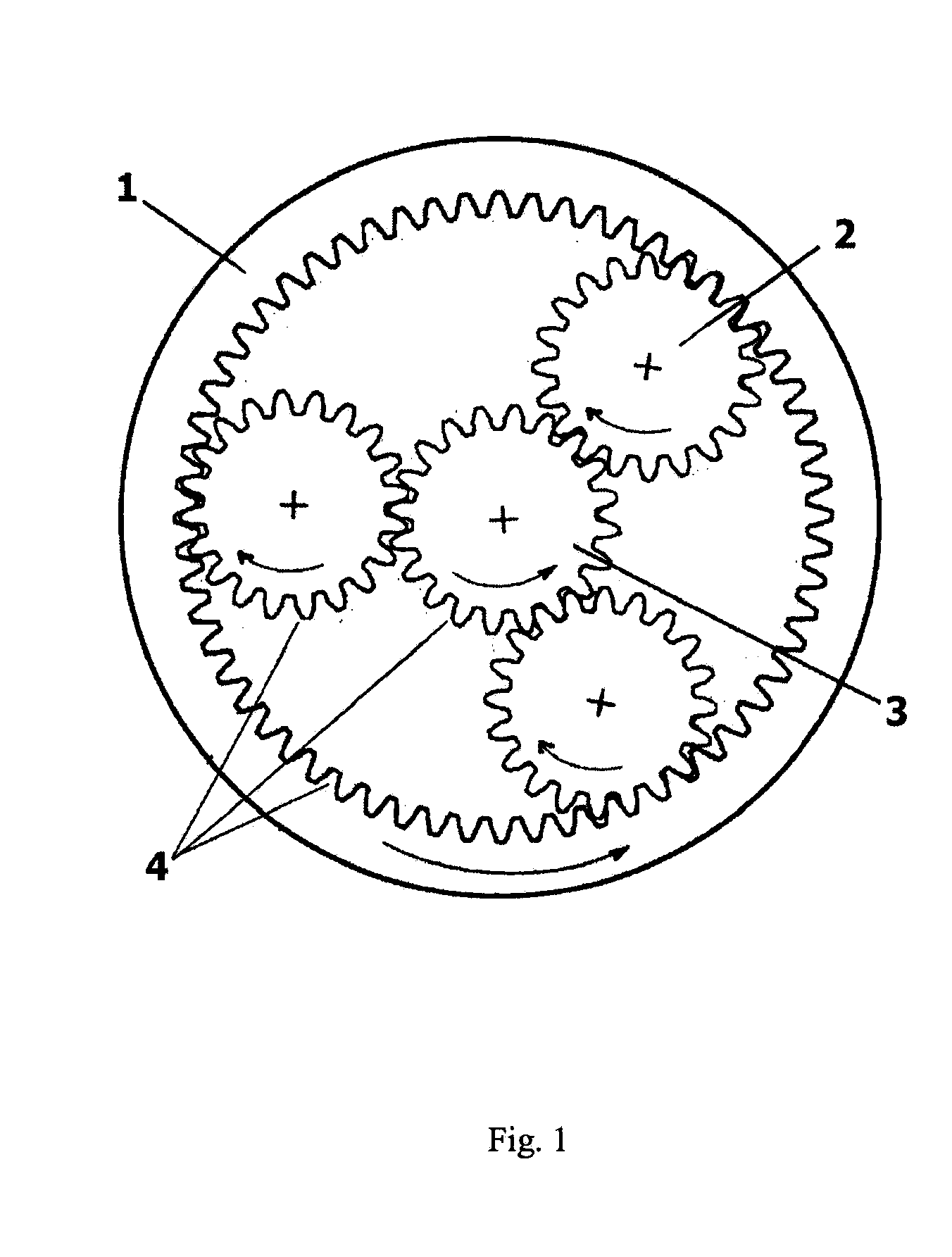
In particular, it was thought that a large hollow wheel gear (annulus gear) weighing from 400 kg to greater than 5000 kg could not be superfinished in a large vibratory bowl.
A person skilled-in-the-art would have predicted that such a massive gear with its relatively small cross sectional area would have immediately sunk to the bottom of the bowl damaging the lining, the gear or both.
In addition, the heavy gear would have been expected to fracture significant quantities of the
ceramic media used in the vibratory finishing equipment because of the
high pressure exerted upon the media.
Instead of
smoothing the critical contact surfaces of the gear teeth to a superfinished condition, these media fragments would have been predicted to damage these surfaces resulting in roughened, gouged and even denting the surfaces, especially nearer the bottom of the bowl where the pressure is greatest.
The anticipated
high rate of media attrition from fracturing would also add an unacceptable
processing cost as well as causing the problem of clogging and blocking the drains of the
processing machine.
Therefore, the vibratory processed hollow wheel gear could end up being out of dimensional tolerance.
It should be mentioned though that turning such a large gear is
time consuming and potentially dangerous.
Also, part of the center width of the gear teeth would be processed for twice the finishing time, possibly causing a
resultant change in the tooth geometry.
Each of the above predicted shortcomings would have been predicted to make this
superfinishing process for large hollow wheel gears commercially impractical and unpredictable.
Therefore, the wind turbine industry could not realize the benefits of this superfinishing process for the input planetary stage of the gear box.
However, removal of the
white layer by
grinding is at great expense and risk to ruining the hollow wheel.
In gas
carburizing, due to the significant
distortion from the heat treatment process, final
grinding of the teeth is required, which is also an expensive process.
Furthermore, after final
grinding, the gas carburized hollow wheel requires temper burn inspection, another hazardous and environmentally unfriendly process.
However, duplicating actual service conditions on a
test rig is not only virtually impossible, but is also impractical as well due to equipment, time and cost constraints.
Unfortunately, even during run-in, this
metal debris can initiate serious damage to the bearings and gear contact surfaces before collection in a filter.
These fine particles still are capable of causing surface damage, particularly to the gear box bearings.
Also, no matter how thoroughly or carefully the run-in procedure is conducted, this process leaves microscopic material distress (stress raisers) on the gear teeth contact regions due to the high stresses created to mechanically shear, fracture or elastically deform the peak asperities.
Micropitting by itself is another source of
metal debris which can cause further damage to the bearings and gear contact surfaces since the metal debris is not immediately or completely trapped by the
filtration system.
Whenever severe wear occurs, the
gear tooth profile is changed leading to increased vibration and
noise which places an elevated stress on the gear box
system.
Additionally, run-in procedures typically only smooth the drive side of the hollow wheel and sun gear while leaving the coast sides of these gear teeth as machined.
During adverse operating conditions such as strong gusts of wind or turbine braking, coast side loading can be high enough to produce asperity contact and contribute to harmful metal debris.
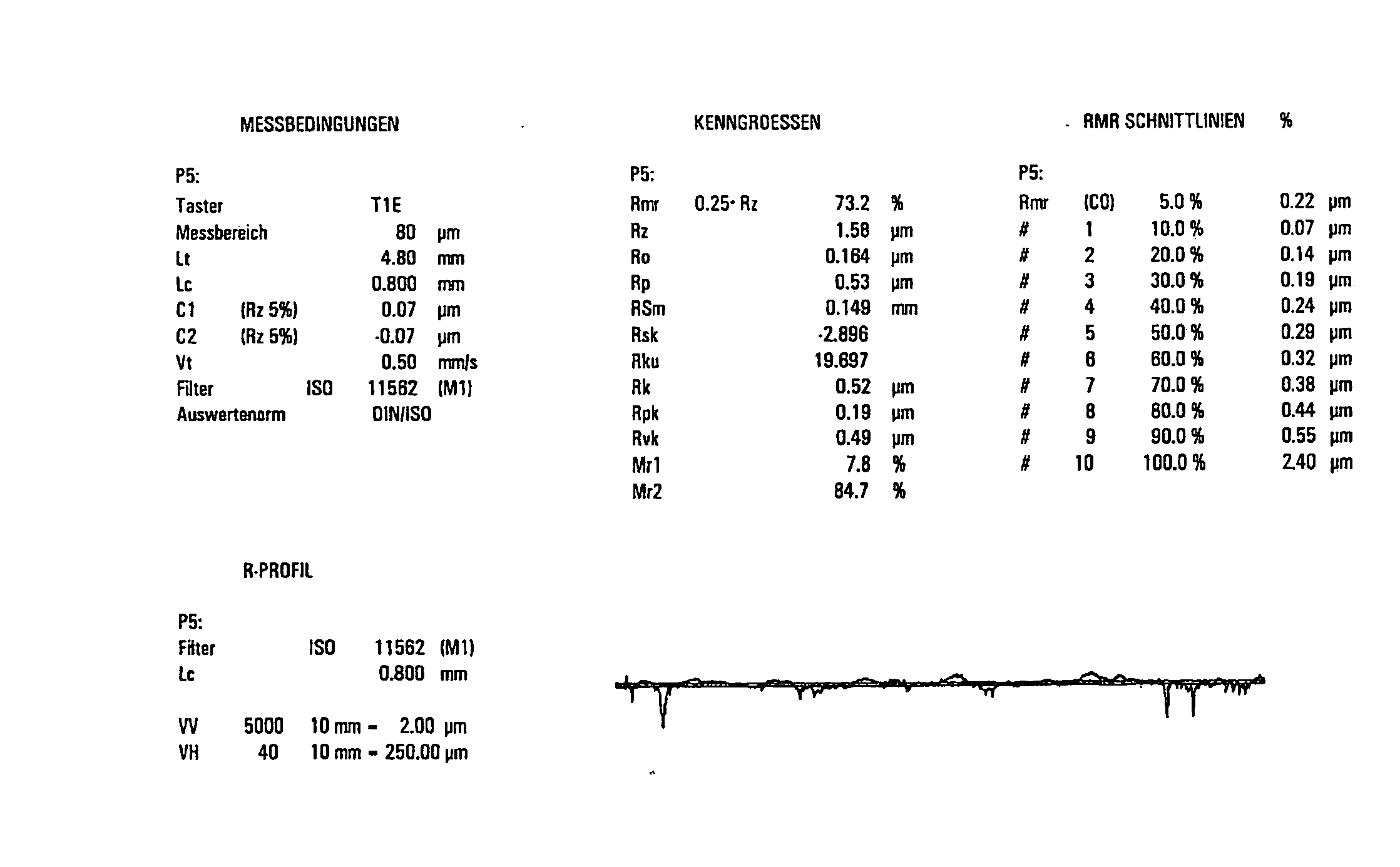
Again, it needs to be emphasized that the industry has failed to give guidance on the actual optimum
surface finish, or on the method of generating such optimum surfaces to improve gearbox durability.

