Method and system for accuracy of speed and acceleration measurements on rotating machinery with a speed wheel

a technology of speed and acceleration measurement and rotating machinery, which is applied in the direction of linear/angular speed measurement, stray field compensation, instruments, etc., can solve the problems of apparent oscillation, non-uniform tooth spacing, and uneven tooth spacing

Active Publication Date: 2008-05-15
GENERAL ELECTRIC CO
View PDF9 Cites 30 Cited by
  • Summary
  • Abstract
  • Description
  • Claims
  • Application Information

AI Technical Summary

Benefits of technology

[0016]It would therefore be desirable to provide an algorithm for calculating the speed of the rotating shaft of the rotating equipment such that oscillation, in the calculated speed that results from non-uniform spacing of gear teeth, is eliminated.

Problems solved by technology

However as shown on a simplified 4 tooth speed wheel in FIG. 2, the distribution of the tooth spacing may not be uniform.
An apparent oscillation will occur in the calculated speed when it is assumed that the tooth spacing is uniform, but the tooth spacing is actually non-uniform.
This speed variation will cause the control system to continuously correct the turbine's speed, and will cause premature, excessive wear of mechanical control components.
This corrective action is not cost effective and undesirable.
The formulas can be changed to use every 2nd, 3rd, 4th TIC, but this results with the same oscillation problem.
At low speeds this lag may be unacceptable.

Method used


Image

  • Method and system for accuracy of speed and acceleration measurements on rotating machinery with a speed wheel
  • Method and system for accuracy of speed and acceleration measurements on rotating machinery with a speed wheel
  • Method and system for accuracy of speed and acceleration measurements on rotating machinery with a speed wheel

Examples


Embodiment Construction

[0026]The embodiments of the present invention have many advantages, including improvement of accuracy of rotation-dependent parameters for rotating machinery provided with a toothed speed wheel.

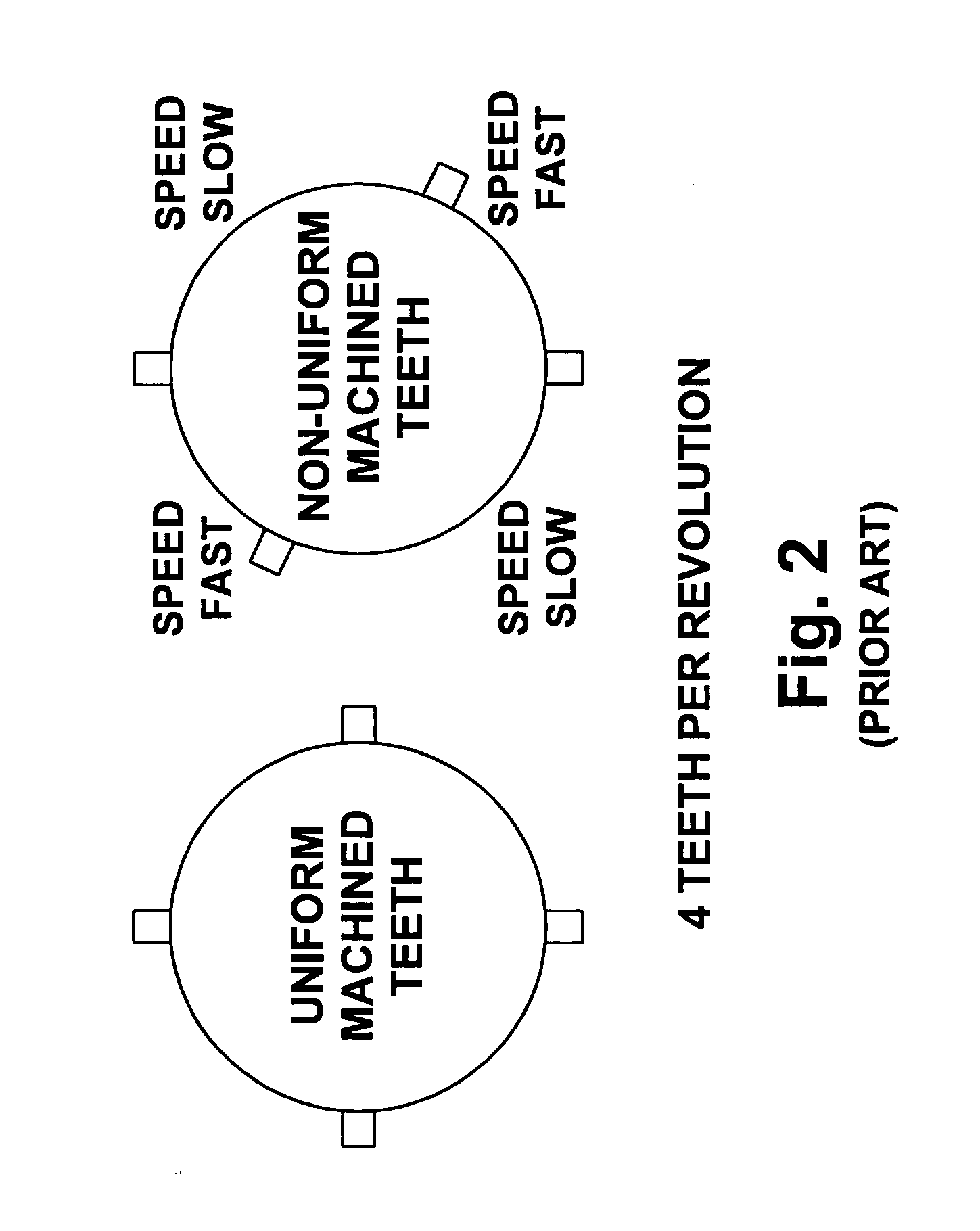
[0027]Compensation may be provided for tooth variations automatically, without physically measuring each tooth or re-machining the speed wheel. Physical spacing from tooth to tooth is determined at the time of manufacture and cannot change. This spacing can be represented as a percent of total wheel. Tooth spacing is also constant, and independent of speed of the shaft

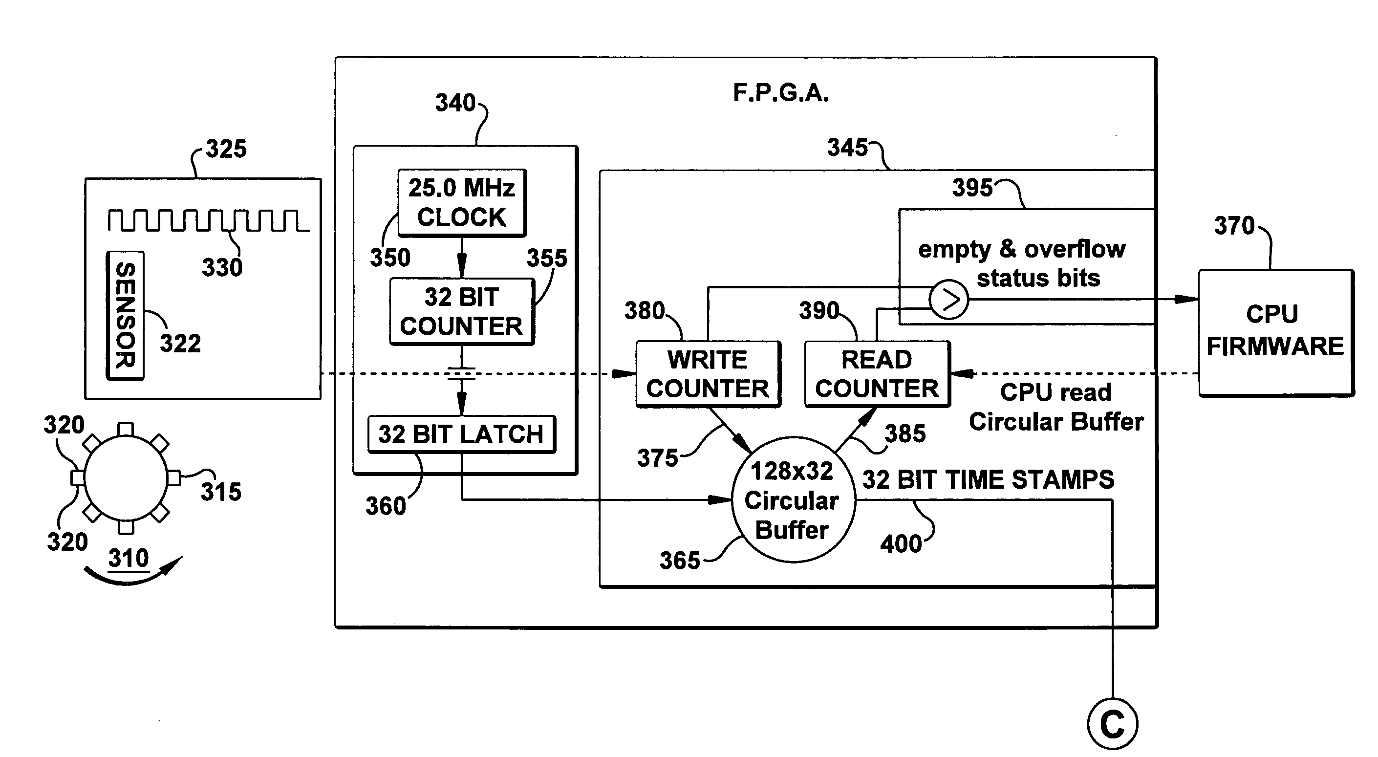
[0028]At a periodic rate of 1 millisecond, the CPU reads the FPGA buffer, and moves all new elements into the CPU's larger circular buffer in memory. A tooth correction (ratio) in a table can be calculated for each tooth in the wheel that passes.

[0029]Provided the turbine and the speed wheel is rotating at a constant speed and the edges for the teeth are evenly spaced around the circumference of the speed wheel, the number of T...


PUM


Abstract

A method and system for calculation of rotation dependent parameters in a system that senses shaft rotation of a toothed speed wheel. The method includes determining the passing edges of multiple gear teeth on a rotating speed wheel; calculating rotational speed of the rotating machine based on the passing edges of multiple gear teeth of the speed wheel; calculating a rotation independent tooth spacing correction factor for each gear tooth on the rotating wheel; and correcting the calculated rotational speed of the rotating machine using the tooth corrections.

Description

BACKGROUND OF THE INVENTION[0001]The invention relates generally to a method and system for improving the accuracy of calculation of rotation dependent parameters in a system that senses multiple pulses associated with shaft rotation and more specifically for improving the accuracy of speed-and acceleration readings from pulse rate sensors on a rotating shaft of rotating equipment, such as turbines. However, the invention is applicable to any rotating device that needs multiple speed, velocity, or acceleration readings per revolution (e.g., engines, generators and drive shafts).[0002]Previous methods for measurement of speed have been addressed, for example, by U.S. Pat. No. 4,434,470 by Robert C. Thomas et al. Thomas et al. describes a method for calculation of speed in Revolutions Per Minute (RPM) using speed pulses. A digital speed measurement circuit for an engine includes a magnetic pick-up positioned adjacent to an engine-driven gear having a substantial number of teeth so the...

Claims


Application Information

Patent Timeline
Patent Type & Authority Applications(United States)
IPC IPC(8): G01L3/00
CPCG01P3/481G01P21/02G01P15/165G01P3/489
Inventor SHAVER, STEPHEN MARKCUNNINGHAM, JOHN N.
Owner GENERAL ELECTRIC CO
Why Eureka
Try Eureka