

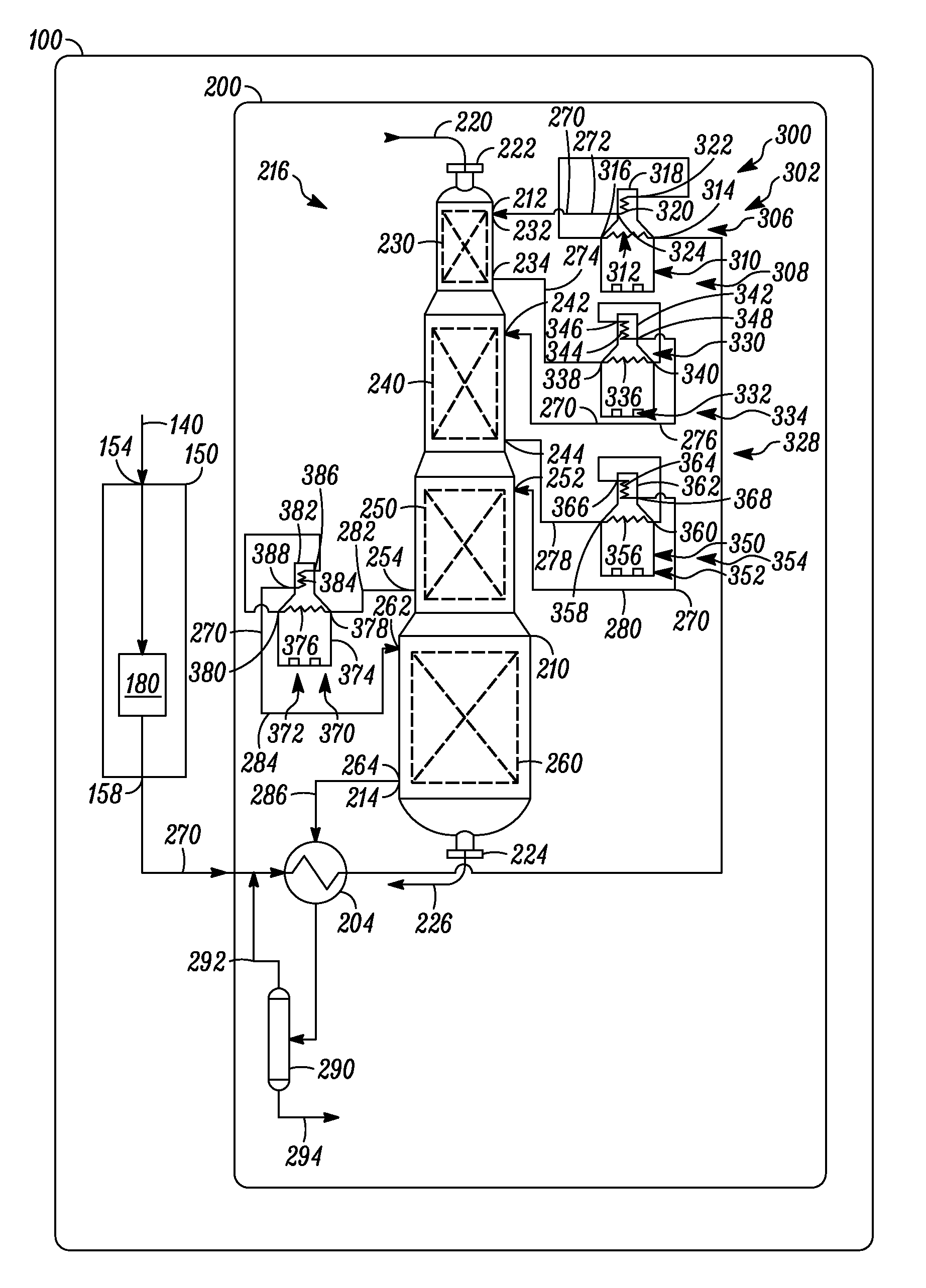
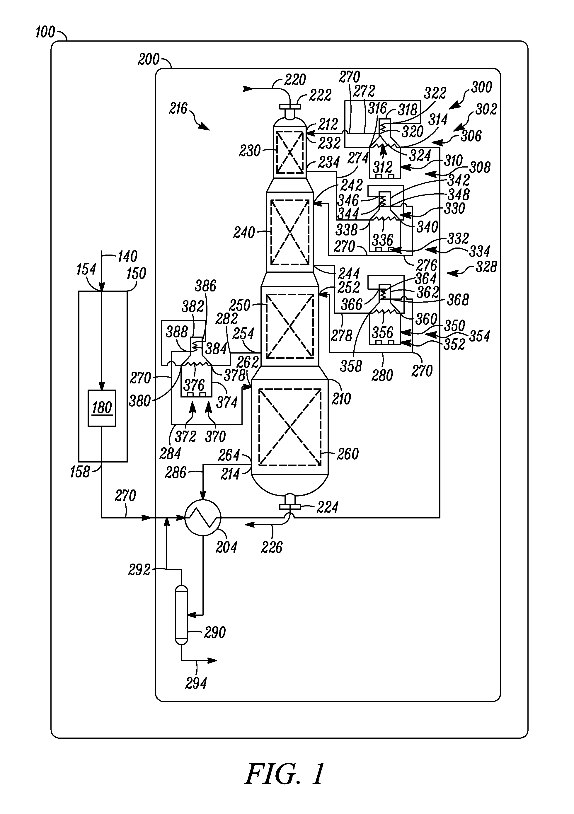
Process For Heating A Stream For A Hydrocarbon Conversion Process
a hydrocarbon conversion and process technology, applied in the field of heating a stream, can solve the problems of high impurity content, limited conversion unit, and disadvantages of conventional designs, and achieve the effects of reducing equipment capital cost and shutdown time, increasing feed rate, and reducing tube wall temperatur
- Summary
- Abstract
- Description
- Claims
- Application Information
AI Technical Summary
Benefits of technology
Problems solved by technology
Method used
Image

Examples
example 1
[0087]The existing first interheater (second heater in a series of heaters) of the reforming unit has a maximum tube wall temperature limitation that prevents an increase in feed rate. In this example, it is desirable that the tube wall temperature be below about 635° C. (about 1,175° F.) Before revamping, the first interheater includes a process coil in the convection section followed, in the direction of flow of the first reaction zone effluent, by a process coil in the radiant section. An analysis of this fired heater cell shows that the calculated maximum tube wall temperature is 639° C. (1,183° F.). By reversing the order of the convection section and radiant sections, i.e. placing the radiant section first followed by the convection section, the maximum tube wall temperature drops to 606° C. (1,123° F.). Additionally, it can then be determined that the charge heater (the first heater in the series) has a maximum tube wall temperature of 638° C. (1,181° F.) for the revamp, and ...
examples 2-5
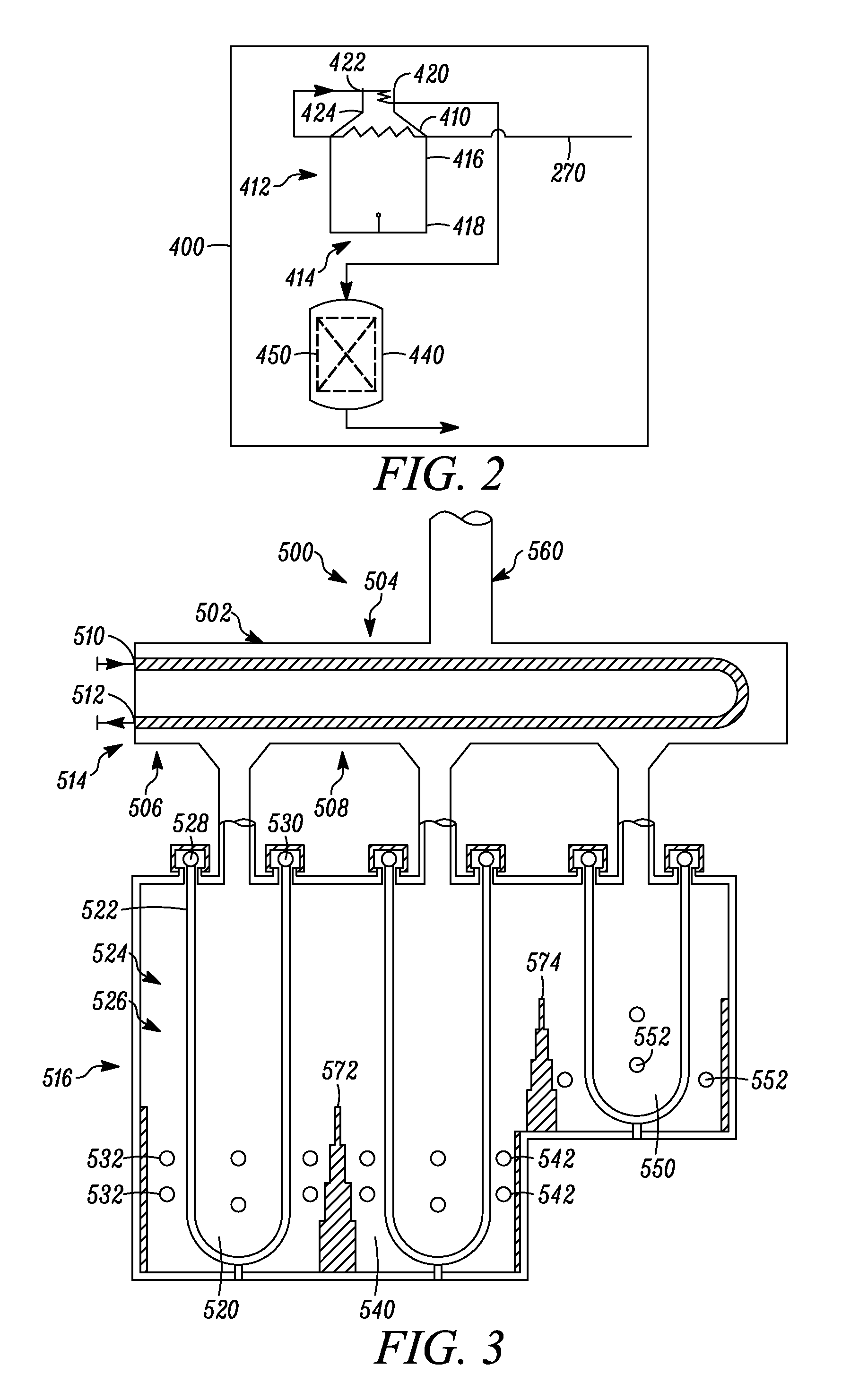
[0088]In this set, an existing heater is analyzed for revamping to meet increased duty requirements. The heater has five radiant cells sharing a common convection section. The common convection section has four rows of tubes, namely rows 1 and 2 in the lower portion of the convection section and rows 3 and 4 in the upper portion of the convection section. These radiant cells are a first charge cell (Cell A), a second charge cell (Cell A1), and three interheater cells (Cell B, Cell C and Cell D with Cell D being initially shutdown). These cells are used to heat the feed to respective reforming reaction zones. Moreover, in these examples it is generally desirable that the maximum tube wall temperature be below about 640° C. (about 1,184° F.).
example 2
[0089]Initially, it is proposed to add a new radiant section as the first interheater (No. 1 IH), as disclosed in the following Table 2:
TABLE 2ChgChgService(first)(second)No. 1 IHNo. 2 IHNo. 3 IHShutdownCellAA1NewBCDFurnaceMax tube wall612 (1,134)658 (1,216)700 (1,292)659 (1,218)N / Aexisting coil,° C. (° F.)
[0090]It is generally more economical to use an existing interheater rather than construct a new one due to a longer turnaround time and a larger capital expense. However, even using a new radiant cell for the first interheater can result in the radiant section of Cells A1, B, and C exceeding the maximum tube wall temperature of 640° C. (1,184° F.). Emphasis added in the above and later tables.
PUM
| Property | Measurement | Unit |
|---|---|---|
| temperature | aaaaa | aaaaa |
| boiling point | aaaaa | aaaaa |
| end boiling point | aaaaa | aaaaa |
Abstract
Description
Claims
Application Information