Amplifier Circuit and Method for Reducing Voltage and Current Noise

a technology of amplifier circuit and current noise reduction, which is applied in the direction of amplifier with modulator/demodulator, amplifier with semiconductor device/discharge tube, amplifier modification to reduce noise influence, etc., can solve the problem of reducing the effective voltage noise in most practical cases, and reduce the effect of amplifier current noise, reduce the effective voltage noise, and reduce the noise contribution to the effect of amplifier voltage nois

Active Publication Date: 2008-05-15
QUANTUM APPLIED SCI & RES
View PDF2 Cites 12 Cited by
  • Summary
  • Abstract
  • Description
  • Claims
  • Application Information

AI Technical Summary

Benefits of technology

[0012]The present invention is directed to a circuit which reduces the effect of amplifier current noise. This circuit also reduces the effective voltage noise in most practical cases. The circuit includes a signal source having an associated impedance producing a signal at a varying frequency. First and second variable impedance devices are provided between a signal source and an amplifier. A modulation frequency generator establishes a modulation frequency to alter the first and second impedance values out of phase from one another at the modulation frequency so that the sum of the first and second impedance values at the input of the amplifier is substantially constant, even while the first and second impedance values are varied. As a result, the modulation at frequency fmod shifts the signal to side bands about the modulation frequency. The modulation frequency is preferably chosen so that the side bands are in a regime at which the noise contribution to the effect of amplifier voltage noise is low. The output from the amplifier is then passed to a bandpass filter centered on the modulation frequency in order to remove all frequencies outside the bandwidth of interest. The signal itself is recovered by demodulating an output for the bandpass filter using a synchronization signal that is derived from the modulation signal. Finally, the demodulated voltage is directed through a low pass filter to generate a sensor output.

Problems solved by technology

This circuit also reduces the effective voltage noise in most practical cases.

Method used


Image

  • Amplifier Circuit and Method for Reducing Voltage and Current Noise
  • Amplifier Circuit and Method for Reducing Voltage and Current Noise
  • Amplifier Circuit and Method for Reducing Voltage and Current Noise

Examples


Embodiment Construction

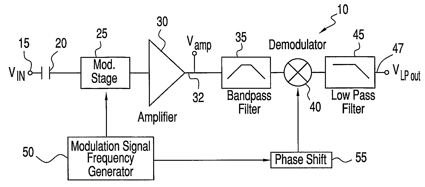
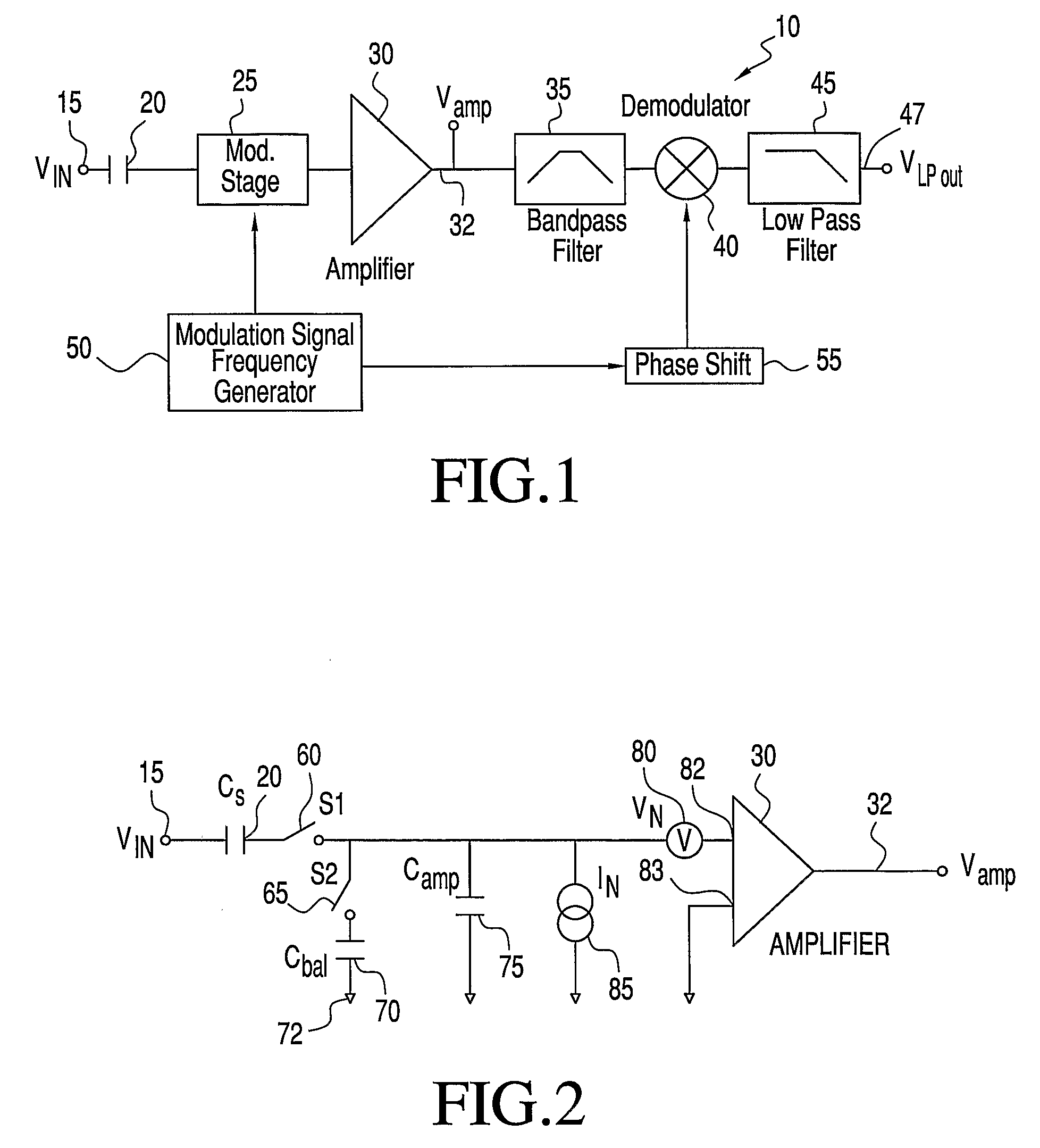
[0026]With initial reference to FIG. 1, there is shown an amplifier circuit 10 with noise reduction constructed in accordance with the present invention. A signal source 15 produces an output signal VIN which is coupled to the rest of the system by a capacitive element 20, preferably constituted by a capacitive sensor or electrode, which measures an electric potential without conducting contact with the potential, or an antenna. Capacitive element 20 is connected to a modulation stage 25 which is buffered by a high input impedance, low noise, low input capacitance amplifier 30. An output 32 of amplifier 30 is connected to a bandpass filter 35. The signal then passes through a demodulator 40 to a low pass filter 45 and finally to an output 47. A modulation signal frequency generator 50 is provided to send a modulation signal to both modulation stage 25 and a phase shift mechanism 55. Input signal VIN is modulated at a frequency fmod which shifts the signal into side bands about the m...


PUM


Abstract

An amplifier circuit with current noise reduction employs first and second variable impedance devices between a signal source and an amplifier. A modulation frequency generator establishes a modulation frequency fmod to alter the first and second impedance values out of phase from one another at the modulation frequency so that the sum of the first and second impedance values at the input of the amplifier is relatively constant. The modulation at frequency fmod shifts the signal to side bands about the modulation frequency. The output from the amplifier is passed to a bandpass filter centered on the modulation frequency in order to remove all frequencies outside the bandwidth of interest. The signal itself is recovered by demodulating the output of the bandpass filter using a synchronization signal that is derived from the modulation signal.

Description

CROSS-REFERENCE TO RELATED APPLICATIONS[0001]The present application claims the benefit of U.S. Provisional Patent Application Ser. No. 60 / 608,366 entitled “System to Reduce Current Noise in High Impedance Circuits and Sensors” filed Sep. 10, 2004.BACKGROUND OF THE INVENTION[0002]1. Field of the Invention[0003]The present invention generally pertains to the art of active electronic devices and, in particular, electronic amplifiers which produce both voltage noise and current noise. More particularly, the invention relates to an amplifier circuit for reducing the effect of current noise at the amplifier input while also reducing the voltage noise in most practical cases.[0004]2. Discussion of the Prior Art[0005]Measurement and amplification systems are sometimes limited by the effect of their internal current noise acting on the impedance of an external element connected to the amplification system. This current noise is multiplied by the impedance of the element to give an effective...

Claims


Application Information

Patent Timeline
Patent Type & Authority Applications(United States)
IPC IPC(8): H03F3/38
CPCH03F1/26H03F3/38H03F3/387H03F3/45475H03F2203/45576H03F2200/372H03F2203/45136H03F2203/45166H03F2200/333
Inventor MATTHEWS, ROBERT
Owner QUANTUM APPLIED SCI & RES
Why Eureka
Try Eureka