
Backlight device, liquid crystal display device, and electronic apparatus

Active Publication Date: 2008-05-15
SATURN LICENSING LLC
View PDF10 Cites 74 Cited by
  • Summary
  • Abstract
  • Description
  • Claims
  • Application Information

AI Technical Summary

Benefits of technology

[0010]Accordingly, it is desirable to provide a backlight device which has a simple structure, which uses fewer parts, and which can be made light, and a liquid crystal display device and an electronic apparatus including the backlight device.
[0011]In addition, it is desirable to provide a backlight device which can efficiently cool heat generated from light-emitting diodes using a simple structure, and a liquid crystal display device including the backlight device.
[0012]According to an embodiment of the present invention, there is provided a backlight device that illuminates a transmissive liquid crystal panel from a rear surface side thereof and that includes a plurality of light source substrates, a reflecting sheet, a diffusing-guiding plate, and an optical-function-sheet layered body. The plurality of light source substrates has a plurality of light-emitting elements for illuminating illumination light. The reflecting sheet has the plurality of light source substrates mounted to one surface of the reflecting sheet, has an opening formed at a location in correspondence with the light-emitting elements mounted to the light source substrates, allows the light-emitting elements to be exposed at another surface of the reflecting sheet from the opening, and reflects the illumination light from the light-emitting elements by the another surface. The diffusing-guiding plate faces the another surface side of the reflecting sheet at a predetermined interval from the reflecting sheet, and diffuses in a layer thereof the illumination light incident from the reflecting sheet. The optical-function-sheet layered body is combined to the diffusing-guiding plate, includes a plurality of laminated optical function sheets, and guides the illumination light to the transmissive liquid crystal panel.
[0015]Here, “directly face” means that there is no other member between the reflecting sheet and the diffusing-guiding plate separating them. By virtue of this structure, since each light source substrate is provided at the first surface of the reflecting sheet so that each light-emitting element is exposed from the second surface, a member for holding each light source substrate required in a related backlight device is no longer required. Therefore, the backlight device is thinner, lighter, and less expensive. In addition, since the reflecting sheet and the diffusing-guiding plate directly face each other, thereby making it unnecessary to provide another member, such as a diffusing plate, between them, it is possible to make the backlight device even thinner, lighter, and less expensive.
[0019]According to the invention, a plurality of light source substrates, having light-emitting diodes that emit illumination light, are mounted to one surface (first surface) of the reflecting sheet that can be used as a basic structure of a backlight unit and that can reflect the illumination light emitted from each light-emitting diode, so that it is possible for the backlight device to have a simpler structure, use fewer parts, and to be lighter.

Problems solved by technology

Therefore, the backlight device disclosed in Patent Document 1 has a double bottom structure formed by the back chassis and the reflecting sheet, thereby making the structure complicated and increasing the weight of the backlight device.
Therefore, in a limited narrow space between the first surface of each light source substrate and the facing reflecting sheet provided directly above the first surface of each light source substrate, a plurality of light-emitting diodes, a wiring pattern, used to wire the light-emitting diodes in series, and wiring parts, such as light source harnesses or connectors, are mounted to the first surfaces of the light source substrates, thereby limiting the degree of design freedom.
Further, since the light source substrates, the heat plate, the heat pipe, the heat sink, etc. are formed using aluminum material, they are heavy, difficult to process, and are expensive.

Method used


Image

  • Backlight device, liquid crystal display device, and electronic apparatus
  • Backlight device, liquid crystal display device, and electronic apparatus
  • Backlight device, liquid crystal display device, and electronic apparatus

Examples


first embodiment

[0029]A first embodiment according to the present invention will be described.

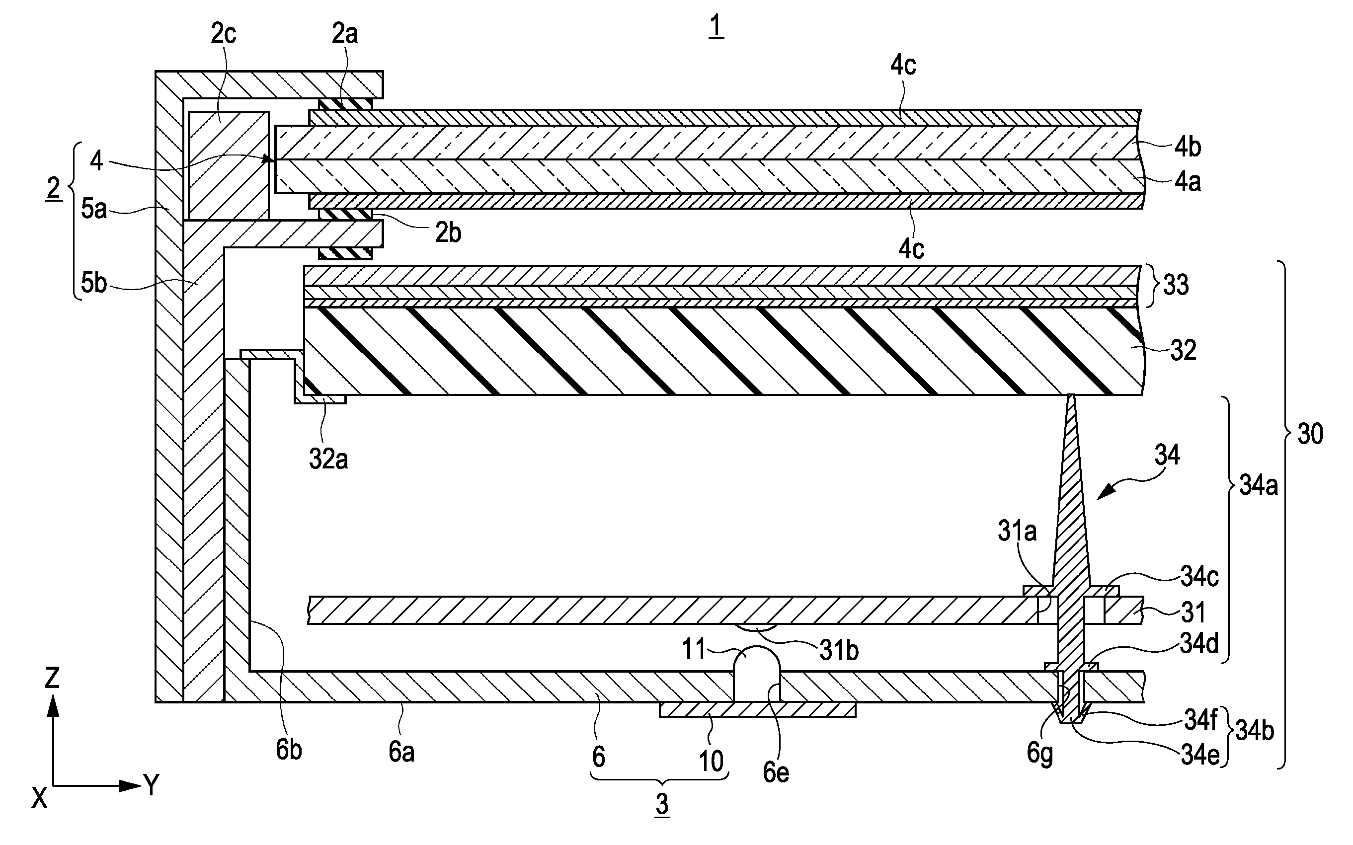
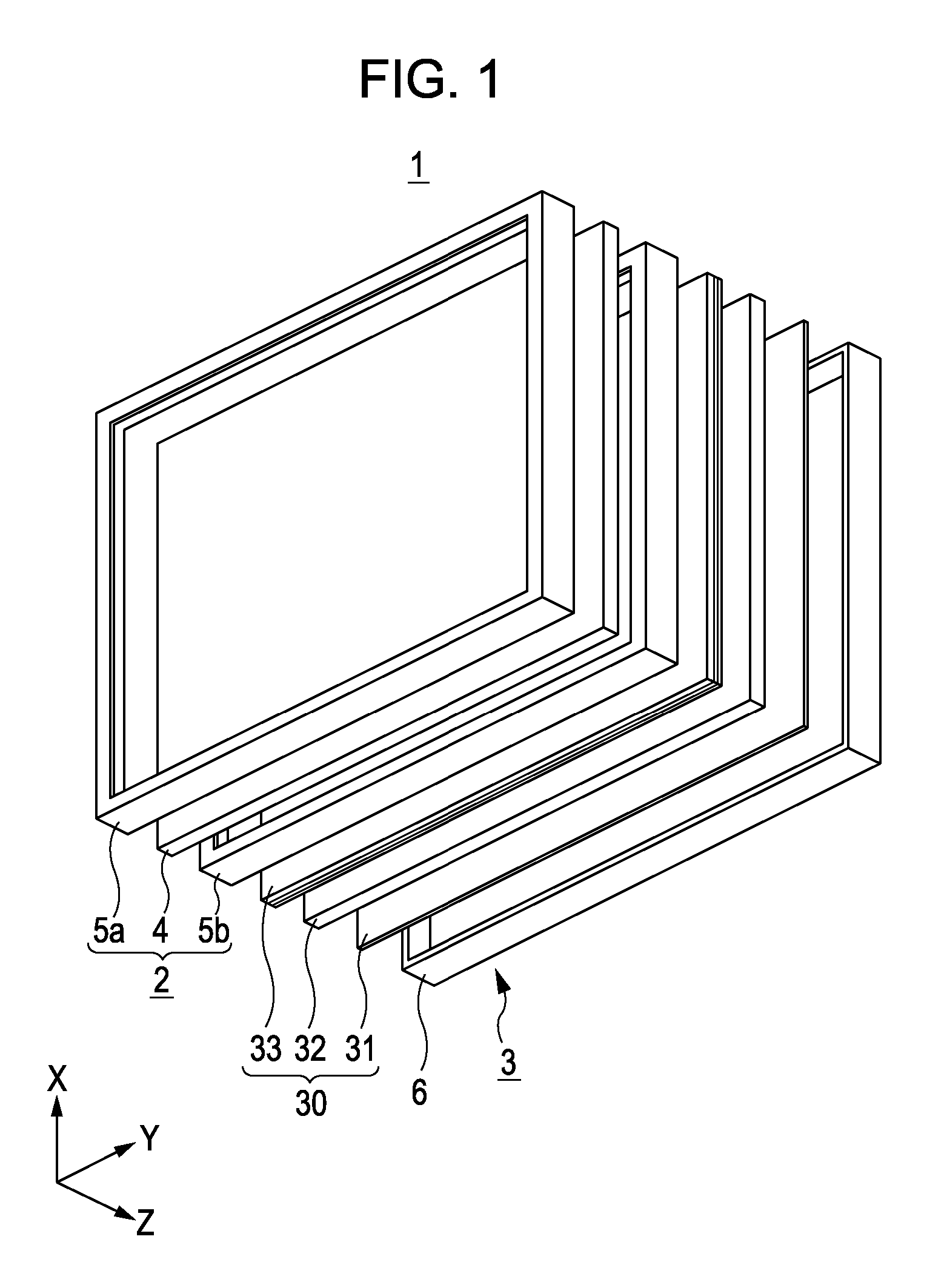
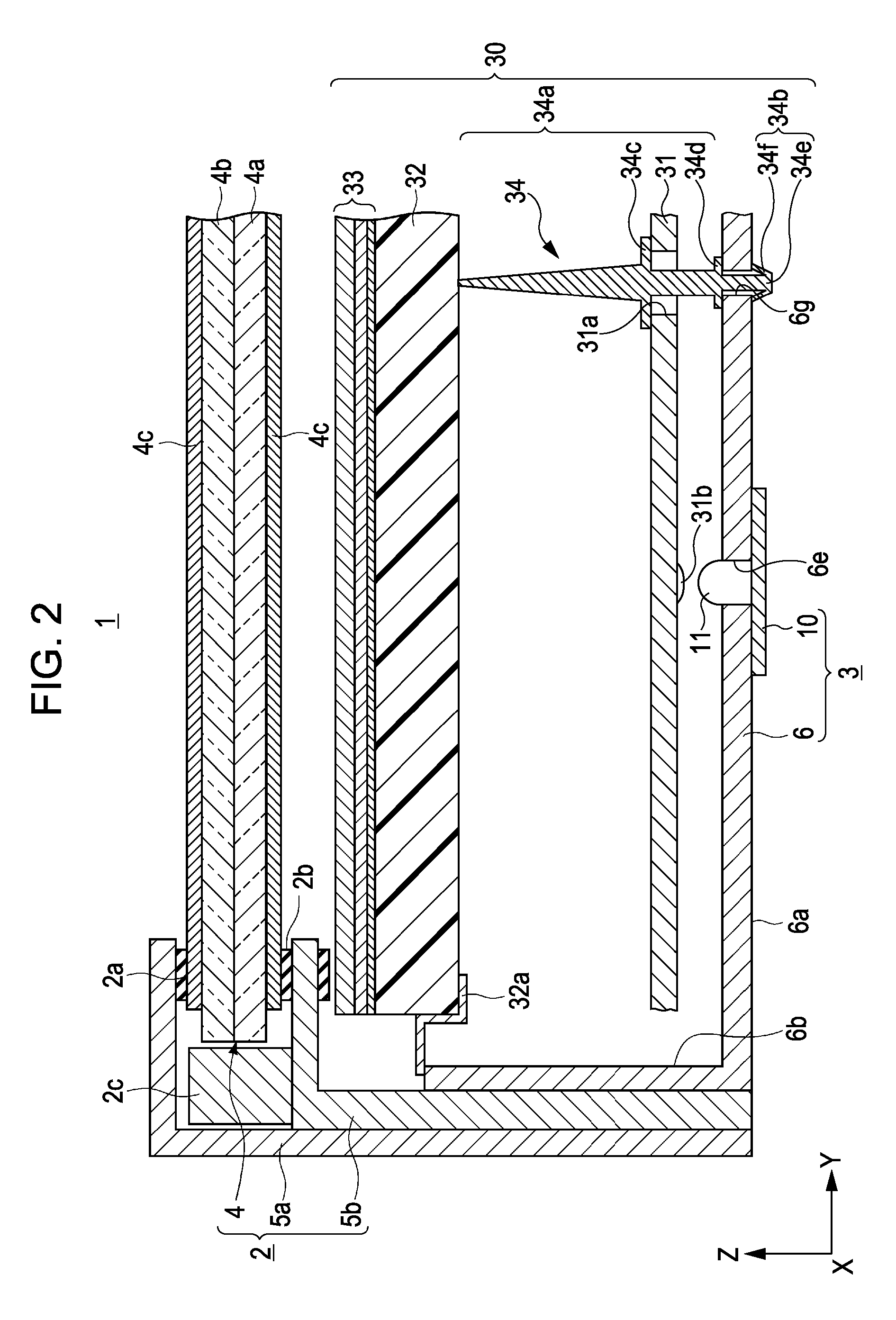
[0030]A liquid crystal display device 1 according to the embodiment is used in, for example, a display panel of a television receiver having a large display screen of at least 40 inches. As shown in FIGS. 1 and 2, the liquid crystal display device 1 includes a liquid crystal panel unit 2, which includes a transmissive liquid crystal panel 4, and a backlight unit 3 to which the present invention is applied, which is combined to the back surface of the liquid crystal panel unit 2 and which illuminates the liquid crystal panel unit 2 with illumination light.

[0031]The liquid crystal panel unit 2 which is illuminated by the backlight unit 3 with illumination light from its back surface includes the substantially rectangular liquid crystal panel 4, and a front frame member 5a and a back frame member 5b, which hold the liquid crystal panel 4.

[0032]As shown in FIG. 2, in the liquid crystal panel 4 held by the fron...

second embodiment

[0080]A second embodiment according to the present invention will be described. Structural portions in the second embodiment corresponding to those in the first embodiment will be given the same reference numerals, and descriptions thereof will be either omitted or simplified.

[0081]FIG. 6 is a vertical sectional view of a main portion of a liquid crystal display device 100 according to the second embodiment. FIG. 7 is a cutaway plan view of a main portion of a reflecting sheet 6 and light source substrates 10 according to the second embodiment. FIG. 8 is a vertical sectional view taken along line VIII-VIII of openings 6e of the reflecting sheet 6 and the light source substrates 10 shown in FIG. 7.

[0082]As shown in FIG. 6, the liquid crystal display device 100 according to the second embodiment differs from the liquid crystal display device 1 according to the first embodiment shown in, for example, FIG. 2, in that the liquid crystal display device 100 does not include a diffusing pla...


PUM


Abstract

A backlight device illuminates a transmissive liquid crystal panel from a rear surface thereof, and includes light source substrates, a reflecting sheet, a diffusing-guiding plate, and an optical-function-sheet layered body. The substrates have light-emitting elements for illuminating illumination light. The reflecting sheet has the substrates mounted to one surface thereof, has an opening formed in correspondence with the light-emitting elements, allows the light-emitting elements to be exposed at another surface of the reflecting sheet from the opening, and reflects the illumination light from the light-emitting elements by the another surface. The plate faces the another surface side of the sheet at a predetermined interval from the reflecting sheet, and diffuses in a layer thereof the illumination light incident from the reflecting sheet. The layered body is combined to the plate, includes laminated optical function sheets, and guides the illumination light to the panel.

Description

CROSS REFERENCES TO RELATED APPLICATIONS[0001]The present invention contains subject matter related to Japanese Patent Application JP 2006-182029 and Japanese Patent Application JP 2007-013149 filed in the Japanese Patent Office on Jun. 30, 2006 and on Jan. 23, 2007, respectively, the entire contents of which are incorporated herein by reference.BACKGROUND OF THE INVENTION[0002]1. Field of the Invention[0003]The present invention relates to a backlight device that illuminates a transmissive liquid crystal panel, and a liquid crystal display device and an electronic apparatus including the backlight device.[0004]2. Description of the Related Art[0005]A liquid crystal display device optically displays, for example, a predetermined image by changing light transmittance as a result of changing the orientation of liquid crystal molecules by applying voltage when liquid crystals are provided between two transparent substrates. Since the liquid crystals, themselves, are not light emitters,...

Claims


Application Information

Patent Timeline
IPC IPC(8): G02F1/1335G02F1/1333F21V29/00H01L33/60
CPCG02F1/133603G02F1/133608G02F1/133606
Inventor SHIBATA, HIROKAZUODE, TATSUYA
Owner SATURN LICENSING LLC
Features
  • Generate Ideas
  • Intellectual Property
  • Life Sciences
  • Materials
  • Tech Scout
  • Unparalleled Data Quality
  • Higher Quality Content
  • 60% Fewer Hallucinations
Learn More