Trans-reflective liquid crystal display and manufacturing method thereof

a technology of liquid crystal display and manufacturing method, which is applied in the direction of optics, electrical appliances, instruments, etc., can solve the problems that the adhesive layer 410 cannot stick well, and achieve the effect of increasing the utility ratio of ligh

Inactive Publication Date: 2008-05-15
CHUNGHWA PICTURE TUBES LTD
View PDF5 Cites 13 Cited by
  • Summary
  • Abstract
  • Description
  • Claims
  • Application Information

AI Technical Summary

Benefits of technology

[0010]For solving the problems mentioned above, an object of this invention is to provide a more efficient reflective film to increase the utility ratio of the light.
[0011]One object of this invention is to provide a more adhesive reflective film to enhance the adhesion, and to solve the peeling issue.
[0012]One object of this invention is to provide an integrated manufacturing process without depositing a metallic reflective layer to reduce the expense of a mask.
[0014]Each reflective film with multi-layer includes at least one unit consisting of a first reflective layer and a second reflective layer which have different refractive indexes, and the unit amount of the reflective film with multi-layer depends on the ratio of the refractive indexes. In general, the first refractive index is larger than the second one. The amount of the layers makes a net reflective index. The more the net reflective index approaches to 1, the higher the utility of the light is.
[0015]The material of the reflective film with multi-layer is similar to that of the dielectric layer. In general, the material is SiNy, SiOx, SiOxNy or the combination thereof. When the x and y are different (the ratio of Silicon, Oxygen and Nitrogen is different), the refractive indexes will be different. Therefore, the net reflective index may approach to 1 by modifying the values of x or y and setting the amount of the layers. And, the adhesion between the reflective film with multi-layer and the dielectric layer will be enhanced due to the similar materials. Moreover, the reflective film with multi-layer and the dielectric layer can be integrated into a process.

Problems solved by technology

However, the reflective layer 600 and the organic insulating layer 500 are made of different materials, and the adhesive layer 410 cannot stick them well.

Method used


Image

  • Trans-reflective liquid crystal display and manufacturing method thereof
  • Trans-reflective liquid crystal display and manufacturing method thereof
  • Trans-reflective liquid crystal display and manufacturing method thereof

Examples


Embodiment Construction

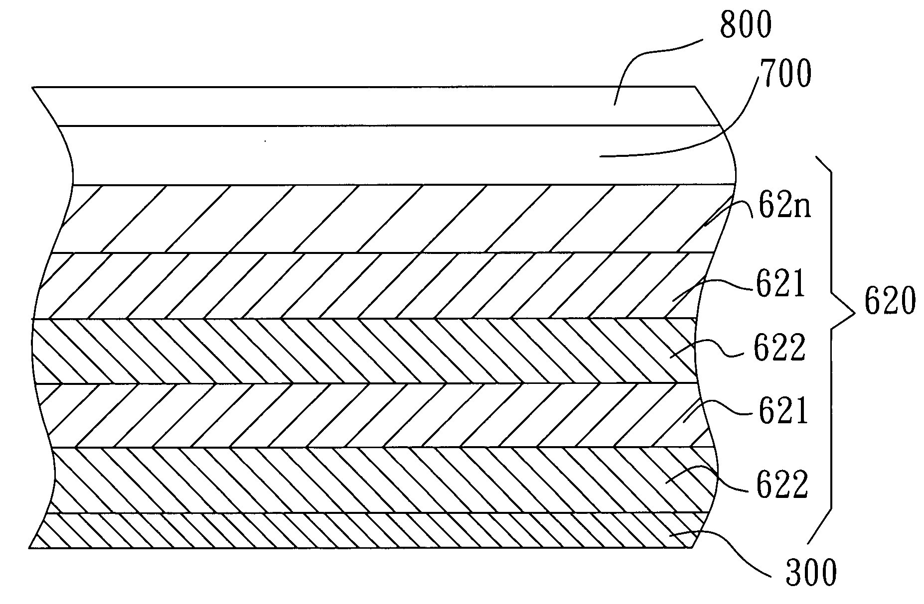
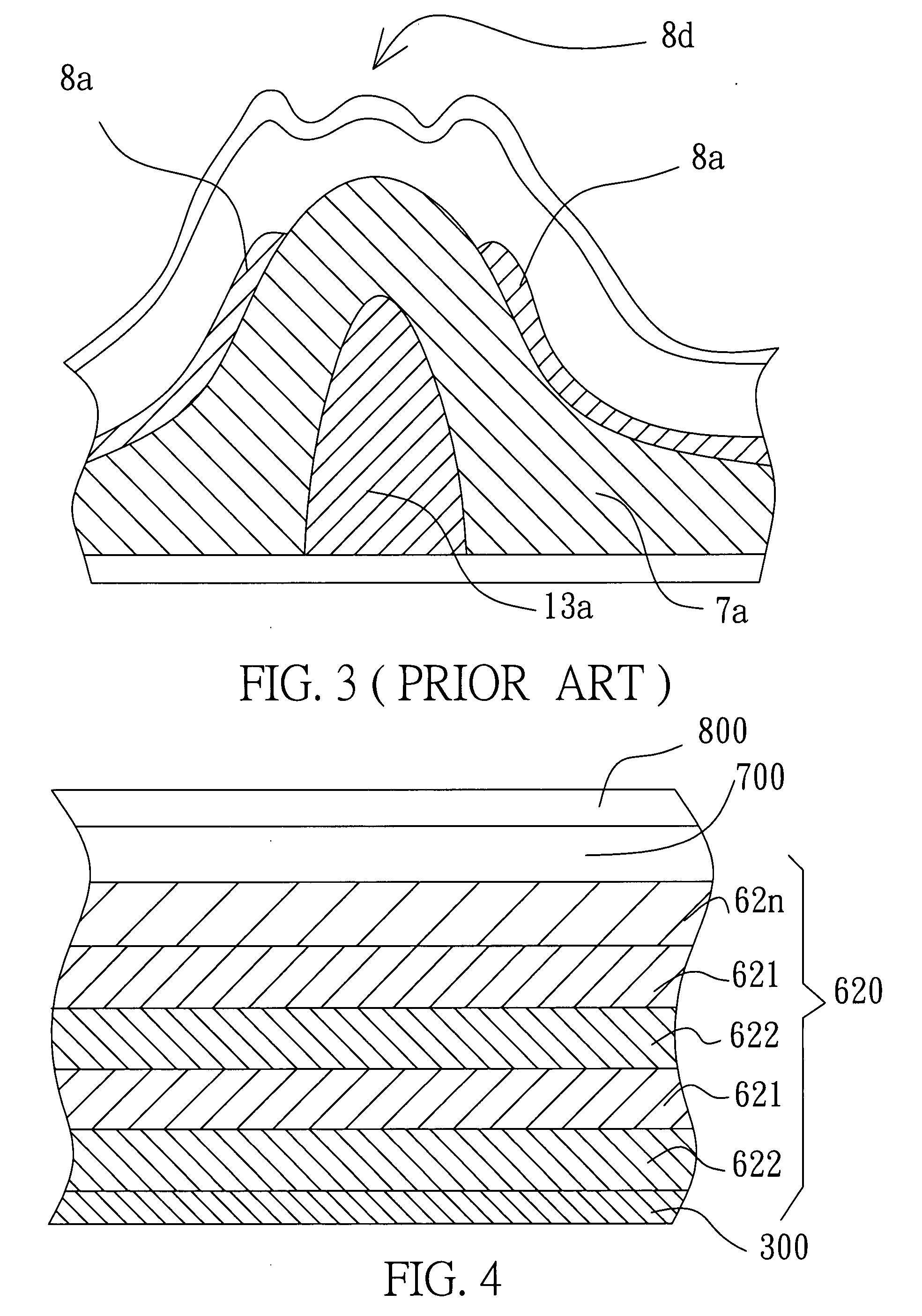
[0026]FIG. 4 shows a sectional view of the reflective area of a trans-reflective LCD according to an embodiment of this invention. A reflective film with multi-layer 620 is stacked on a dielectric layer 300, and each reflective film with multi-layer 620 includes at least one unit consisting of a first reflective layer 621 and a second reflective layer 622 which have different refractive indexes. For better understanding this invention, as shown in FIG. 4, a reflective layer 62n represents the non-physical structure of the reflective film with multi-layer, and the sequential stacked layers represent a liquid crystal layer 700 and a color filter substrate 800.

[0027]The reflective film with multi-layer 620 and the dielectric layer 300 are made of the similar materials, such as the silicon nitride SiNy, the silicon oxide SiOx, silicon nitro oxide SiOxNy or their combination. When x and y are different (it means the ratio of the Si, O and N be different), the refractive index is differen...


PUM

PropertyMeasurementUnit
refractive indexaaaaaaaaaa
transparentaaaaaaaaaa
semi-transparentaaaaaaaaaa

Abstract

The structure of a trans-reflective liquid crystal display panel includes stacks in longitudinally and two areas in transversely, which are reflective area and transmissive area. A thin-film-transistor layer and a dielectric layer are formed on a substrate in sequential. For the transmissive area, a transparent conductive film, such as a pixel electrode, is formed. For the reflective area, a reflective film with multi-layer is formed on the dielectric layer and then the thin-film-transistor layer. After assembling, the trans-reflective liquid crystal display is complete. The materials of the reflective film with multi-layer and the dielectric layer are similar to have greater adhesion. Each layer of the reflective film with multi-layer includes two sublayers, the first reflective sublayer and the second reflective sublayer, which have the different refractive indexes. By modifying the temperature, pressure, gas flow and power of emitting in manufacturing process can make the refractive indexes of both layers.

Description

FIELD OF THE INVENTION[0001]This invention relates to a trans-reflective liquid crystal display and the manufacturing method thereof, and more especially, to a reflective film with multi-layer in a trans-reflective liquid crystal display and its manufacturing method.BACKGROUND OF THE RELATED ART[0002]A trans-reflective liquid crystal display (LCD) utilizes the incident light from front panel, and the light from a backlight module as its light source. In manufacturing, a reflective film is deposited on the partial substrate to reflect the incident light which is to provide a portion of light source for the LCD panel. Therefore, the other portion of light source is from the backlight module for the LCD panel.[0003]FIG. 1 is a sectional diagram showing a conventional trans-reflective LCD with double cell gaps, and the LCD panel is divided into a transmissive area and a reflective area as shown in this longitudinal sectional view. The structure of the LCD panel is to form thin film tran...

Claims


Application Information

Patent Timeline
Patent Type & Authority Applications(United States)
IPC IPC(8): H01L21/02G02F1/1335
CPCG02F1/133553G02F2202/42G02F1/1362
Inventor SU, TA-JUNGCHANG, YU-WEICHIANG, MING-SHENG
Owner CHUNGHWA PICTURE TUBES LTD
Why Eureka
Try Eureka