
Open mold manufacturing process with centralized application station

a manufacturing process and application station technology, applied in lighting and heating apparatus, heating types, ventilation systems, etc., can solve the problems of inability to meet environmental regulations, inconvenient operation, and inability to meet the requirements of the current manufacturing facility, so as to minimize the volatilities of the manufacturing process and the small footprint of the facility

Inactive Publication Date: 2008-05-15
MASCO BATH CORP
View PDF16 Cites 0 Cited by
  • Summary
  • Abstract
  • Description
  • Claims
  • Application Information

AI Technical Summary

Benefits of technology

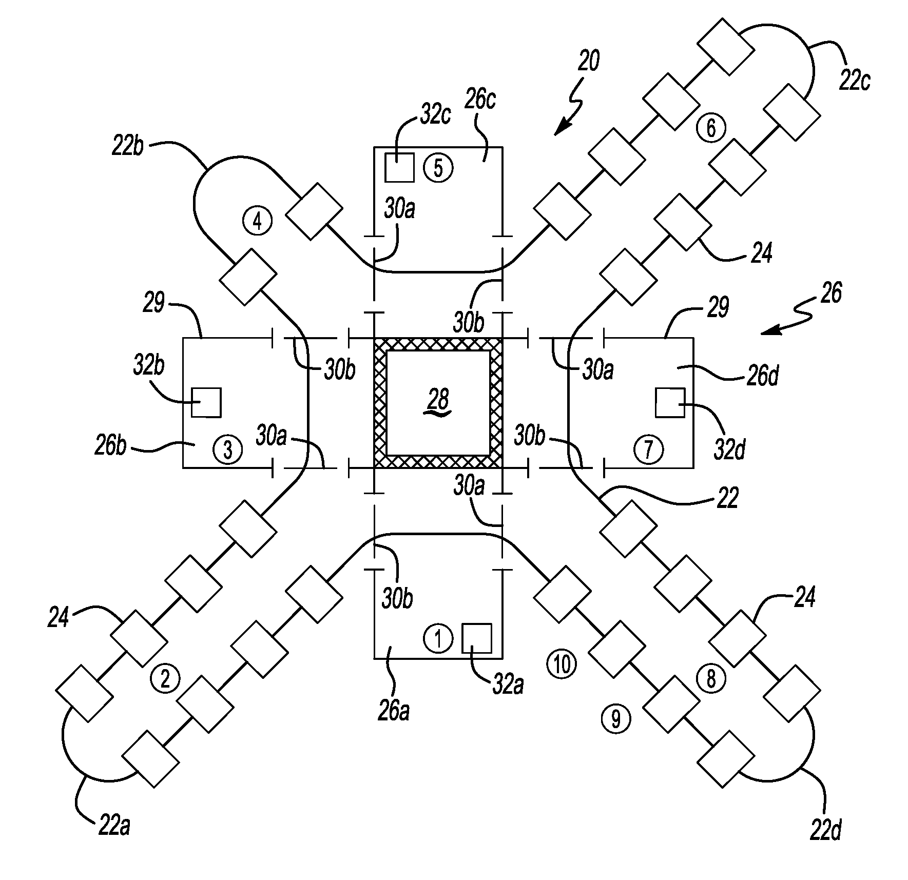
[0011] All spray operations occur within a central spray booth. The booth surrounds a common exhaust plenum. The high concentration of spraying and the associated low airflow requirements provides for more effective utilization of expensive environmental emission control devices. Moreover, as the spray Zones utilize the common exhaust plenum, a large number of spray operations (higher airflow lower spraying concentration) along a conventional assembly line type molding system are replaced by the centralized booth having low airflow and high spraying concentrations. Application of exceedingly expensive environmental emission control devices is therefore at least partially mitigated by the centralized spray booth in which low airflow requirements effectively remove the emissions and provide a much smaller factory footprint.
[0013] The present invention therefore provides an open mold manufacturing process which meets stringent environmental regulations within a small footprint facility. The present invention also minimizes manufacturing process volatilities due to exogenous and human variables in a cost effective manner.

Problems solved by technology

Environmental regulations are becoming more and more inflexible.
The expense of providing environmental emission control devices which meet environmental regulations often results in cost prohibitive manufacturing facilities.
Often older facilities become non-compliant and must be idled.
The expense of the regulation may be particularly high for an assembly line type molding system as spraying occurs at multiple locations along the assembly line.
The entire facility is therefore typically subjected to particularly harsh environmental regulations.
Assembly line type molding systems require a rather large manufacturing facility footprint as a curing station follows each spraying station.
Multiple lengthy curing stations greatly lengthens the assembly line.
A larger manufacturing facility is subject to harsher environmental regulations than a smaller facility.
Each spray station is vulnerable to many exogenous variables that are difficult to control in a cost effective manner.
Many individual operators, even though highly trained, still may create manufacturing process volatilities due to variance in human technique and process manipulation.
However, this may simply result in many robotic spray stations replacing many human spray stations without a substantial reduction in expense.

Method used


Image

  • Open mold manufacturing process with centralized application station
  • Open mold manufacturing process with centralized application station
  • Open mold manufacturing process with centralized application station

Examples


Embodiment Construction

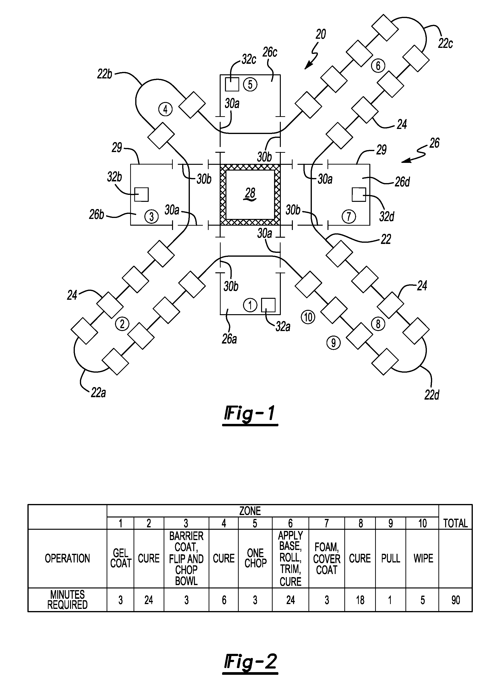
[0018]FIG. 1 illustrates a factory layout for a mold manufacturing system 20. System 20 is preferably utilized for open molding of large parts, and in particular bath tubs and shower surrounds. The system 20 includes a circuit 22 upon which a multiple of molds 24 transit a closed loop. The molds 24 preferably hang from an overhead rail system such that access is readily provided to the entire mold outer surface. Other transit systems such as conveyors, tracks, guided vehicles and the like will also benefit from the present invention.

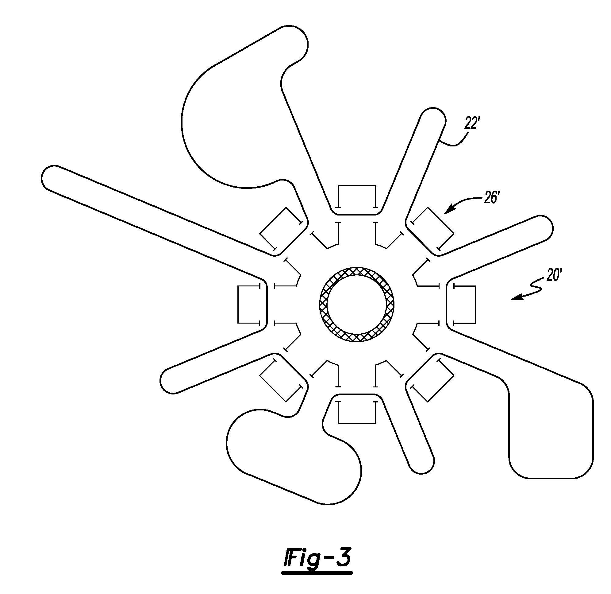
[0019] The circuit 22 preferably defines an elongated cross like circuit in which the molds 24 move toward a spray booth 26, through the spray booth 26 and away from the spray booth 26 a multiple of times. In other words, the spray booth is a hub and the rail circuit is a closed circuit of radially extending spokes. Spraying occurs within the booth 26 a multiple of times during a single lap. It should be understood that although described as a “spray” o...


PUM

PropertyMeasurementUnit
distanceaaaaaaaaaa
areaaaaaaaaaaa
perimeteraaaaaaaaaa

Abstract

A mold manufacturing system includes a conveyer circuit upon which a multiple of molds transit a closed loop and repetitively pass through a central booth. The system is separated into Zones in which a particular mold operation is performed. Each of a multiple of applying operations are performed within the central booth which contains a common exhaust plenum. Application of exceedingly expensive environmental emission control devices is at least partially mitigated. Consolidation of multiple spray operations into a few spray Zones also advantageously simplifies the control of chemical and ambient variables which improves production efficiencies and reduces operator dependency.

Description

[0001] The present invention is a divisional application of U.S. application Ser. No. 10 / 146,275, filed May 15, 2002.BACKGROUND OF THE INVENTION [0002] The present invention relates to an open mold manufacturing process, and more particularly to a manufacturing system in which molds make a single lap while passing through a centralized application station a multiple of times. [0003] Open mold fiberglass reinforced plastic molding systems are well known. Molds typically travel along a linear assembly line. A plurality of operations are performed at stations along the assembly line until a finished part is removed from the mold at the end of the assembly line. [0004] Multiple stations along the assembly line are spray stations. As the molds transit the spray station a particular spraying operation is performed. Such spray operations include gelcoat and resin / catalyst / chopped fiberglass fixture application. Multiple coats are often required for one or more spraying operations necessita...

Claims


Application Information

Patent Timeline
Patent Type & Authority Applications(United States)
IPC IPC(8): F24F7/00B29C33/36B29C39/02B29C70/30B29C70/38
CPCB29C33/36B29C70/305B29C39/025
Inventor BROWN, CHARLES M.
Owner MASCO BATH CORP
Learn More