Burner Control Sensor Configuration

a sensor configuration and burner technology, applied in combustion control, combustion regulation, fuel supply regulation, etc., can solve problems such as system errors registered

Inactive Publication Date: 2008-05-15
NUVERA FUEL CELLS
View PDF10 Cites 25 Cited by
  • Summary
  • Abstract
  • Description
  • Claims
  • Application Information

AI Technical Summary

Problems solved by technology

If the difference between any two outputs of different sensors exceeds a predetermined value, then a “system error” is registered.

Method used


Image

  • Burner Control Sensor Configuration
  • Burner Control Sensor Configuration

Examples


Embodiment Construction

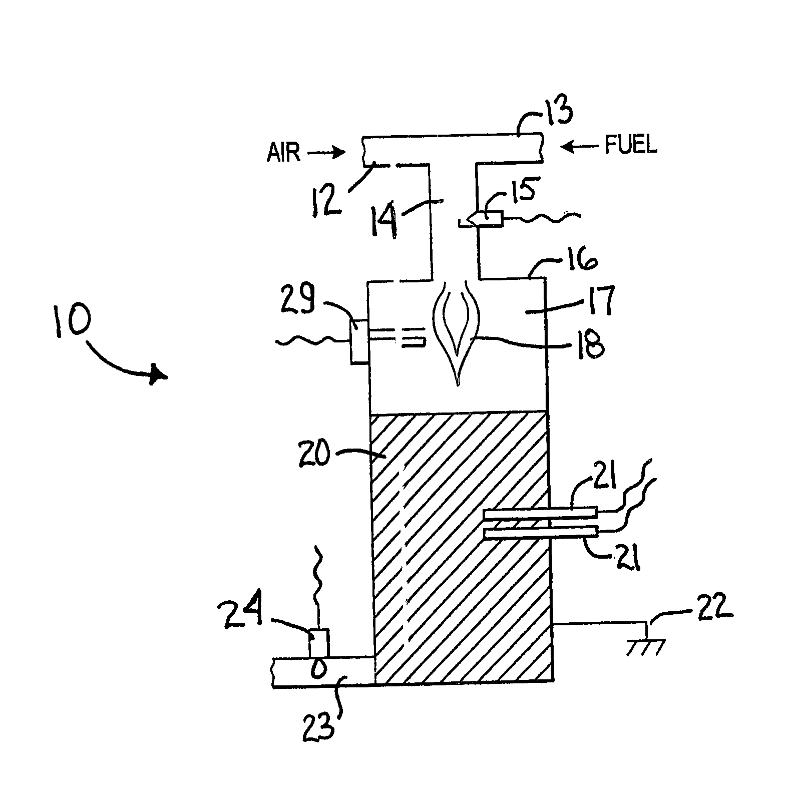
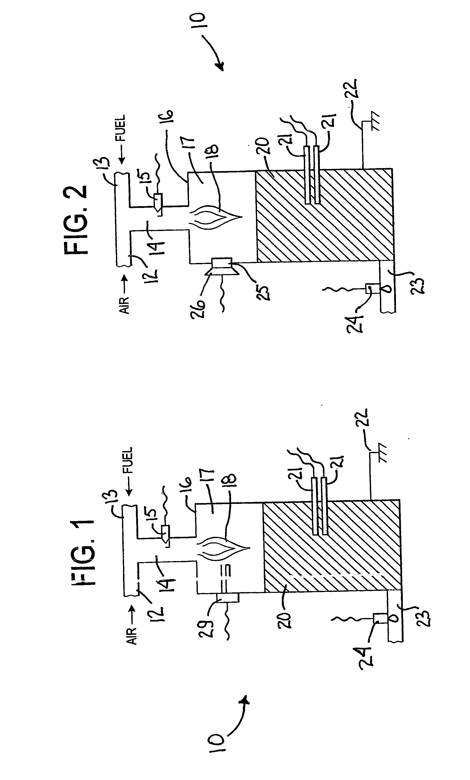
[0025]In this application, the term “burner” and the phrase “tail gas combustor” are used interchangeably to describe a vessel where the combustion of fuel and air takes place to generate heat. The term “fuel” includes any hydrocarbon, alcohol, reformate stream, unreacted hydrogen from a fuel cell stack, and reformate from a fuel cell stack. “Air” includes any oxygen containing gas suitable for use in a burner. Likewise, “hydrogen” includes any hydrogen containing gas suitable for use in a burner, and in particular pure hydrogen and reformate. “Reformer” includes any catalytic vessel responsible for the production of hydrogen by a steam reforming reaction.

[0026]The present invention describes methods and apparatus for demonstrating proof of combustion within a burner or tail gas combustor of a fuel processing system in a fuel cell power plant. This process may be generally referred to in the following description as verifying (-ication), validating, demonstrating, proving, and evide...


PUM


Abstract

In domestic installations of any type of furnace or equivalent, proof of lean combustion is necessary to satisfy requirements of certification agencies. Exhibiting proof of lean combustion during the operation of an integrated fuel reformer and fuel cell system can be problematic because the point of combustion and its nature may shift during operation. In addition, the preferred ratio of fuel to air in these fuel-reforming systems is often near a stoichiometry of one. In the present invention, the combination of a flame-detecting device, a temperature sensing device and an oxygen or hydrocarbon sensor is used to verify the occurrence of combustion, and show proof of lean combustion.

Description

RELATED APPLICATION[0001]The present application is related to and claims priority of U.S. Provisional Application Ser. No. 60 / 524,986 filed Nov. 25, 2003.FIELD OF INVENTION[0002]The field of invention pertains to combustion detection within a burner or tail gas combustor that is part of a fuel processing system comprising a fuel reformer and a fuel cell.BACKGROUND[0003]Hydrogen, which is used in fuel cells, is most commonly created by steam reforming. The steam reforming reaction in a fuel processing system is endothermic, meaning heat is absorbed by the reaction. Therefore, heat needs to be supplied to the system to drive the reaction. In “pure” steam reforming, heat is supplied from an outside source to a catalyst bed. In “partial oxidation” and “autothermal reforming,” heat is created within the catalyst bed by oxidation of some fuel with air.[0004]The need to transport heat from an outside source to a catalyst bed can be an obstacle to rapid startup or rapid change of operating...

Claims


Application Information

Patent Timeline
Patent Type & Authority Applications(United States)
IPC IPC(8): F23N5/10F23N5/00F23N1/02F23N5/24
CPCF23C2900/03002F23N1/022F23N5/006F23N5/102F23N2041/14F23N2027/16F23N2029/16F23N2037/12F23N5/242F23N2227/16F23N2229/16F23N2237/12F23N2241/14
Inventor VEASEY, JOEY DEWAYNELEEHEY, JONATHAN R.RIZZO, VINCENT G.
Owner NUVERA FUEL CELLS
Why Eureka
Try Eureka