Dental implant for supporting a dental prosthesis

a dental implant and prosthesis technology, applied in dentistry, dental surgery, medical science, etc., can solve the problems of dental prosthesis sinking deeper into the jaw bone the longer it continues, unable to use conventional dental implants, and only with a considerable effort, and achieves a small volume, simple structure, and small dimension.

Inactive Publication Date: 2008-05-15
STRAUMANN HLDG AG
View PDF17 Cites 13 Cited by
  • Summary
  • Abstract
  • Description
  • Claims
  • Application Information

AI Technical Summary

Benefits of technology

[0006]By virtue of its simple structure, the dental implant according to one embodiment of the invention can be produced in small dimensions and inexpensively. The dental implant can therefore also be used in free-end gaps and in cases where there are particularly flat alveolar ridges presenting only a small quantity of bone. By virtue of the cylindrically symmetrical main body, known drilling techniques can be employed for installation into the jaw bone.
[0007]The dental implant system according to one embodiment of the invention comprises, in addition to the dental implant, a dental drill with a drill stop for particularly simple production of an implant-specific recess in the jaw bone, and an anchor element that can be mounted on the dental implant. The anchor element makes it possible to produce a releasable connection between the dental implant and the tooth prosthesis and thus permits, in addition to the supporting function, a securing function.

Problems solved by technology

Particularly at the rear free-end gaps, or in cases of particularly flat alveolar ridges presenting a small quantity of bone, the use of conventional dental implants is not possible, or is possible only with quite considerable effort.
The normal masticatory forces can also lead to the dental prosthesis sinking deeper into the jaw bone the longer it continues to be used.
This results in the gum beneath the dental prosthesis being compressed, which can lead to extremely unpleasant pain for the person wearing the dental prosthesis.
This can be expected to lead to bone degeneration and, consequently, to a lack of support of the posterior teeth and to joint changes.

Method used


Image

  • Dental implant for supporting a dental prosthesis
  • Dental implant for supporting a dental prosthesis
  • Dental implant for supporting a dental prosthesis

Examples


Embodiment Construction

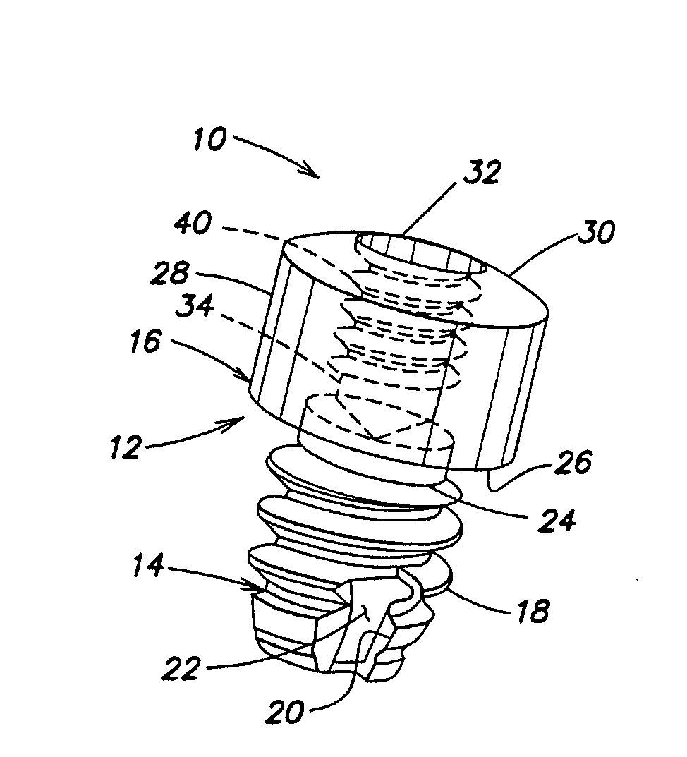
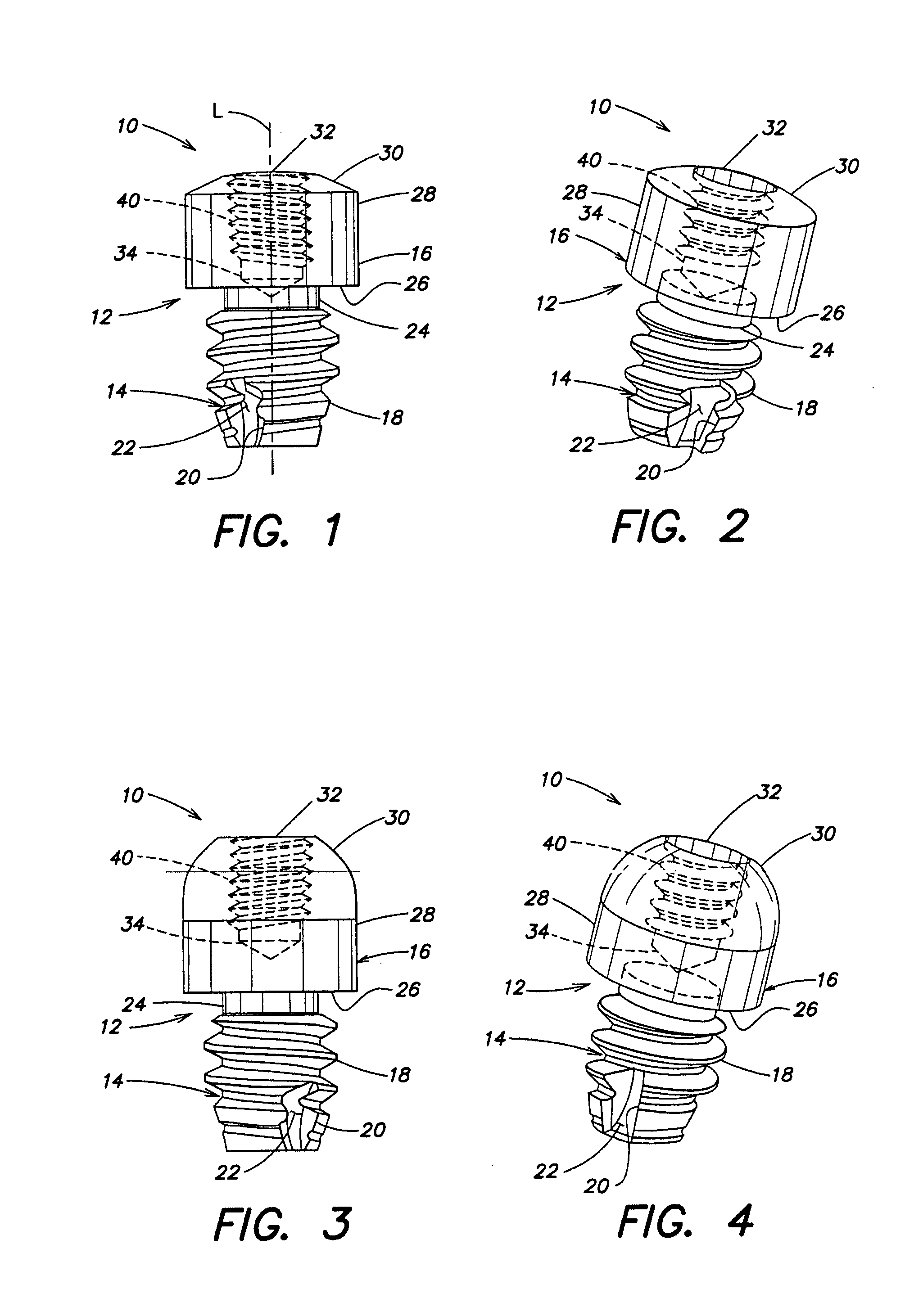
[0019]The dental implant 10 according to one embodiment of the invention shown in FIGS. 1-4 comprises a substantially cylindrically symmetrical, screw-like main body 12, which is divided into a securing portion 14 and a head portion 16. The securing portion 14 is provided with a self-cutting outer thread 18 and is used for anchoring in the tissue of a jaw bone. The self-cutting property of the outer thread 18 is achieved by cutting edges 20, which partially delimit a groove 22 in the outer thread 18. The groove 22 is used to guide tissue material away while the dental implant 10 is being screwed into the jaw bone, and it makes the dental implant 10 easier to screw in. In the securing portion 14, at the end toward the head portion, the outer thread 18 is adjoined by an undercut 24 which, for production reasons, is not provided with thread turns.

[0020]The head portion 16 is mushroom-shaped, and its cross section protrudes radially beyond the cross section of the securing portion 14 to...


PUM


Abstract

Dental implant (10) for supporting a dental prosthesis on a jaw bone, is equipped with a main body (12), which comprises a securing portion (14) intended to be anchored in the bone tissue and, lying opposite it, a head portion (16). The head portion (16) protrudes radially beyond the securing portion (14) with respect to the longitudinal axis of the main body (12) to form a support face (26), in such a way that, in the state of insertion in the jaw bone, the pressure of the dental implant (10) on the jaw bone is reduced, and a sinking movement of the dental implant (10) into the jaw bone is effectively avoided, even over quite long periods of time.

Description

FIELD OF THE INVENTION[0001]The present invention relates to a dental implant for supporting a dental prosthesis on a jaw bone and to a dental implant system including said dental implant.BACKGROUND[0002]Removable dental prostheses are usually fixed releasably to the jaw using so-called adhesive creams or mechanically on the residual dentition, which is equipped with special anchor elements for connection to the dental prostheses. Particularly at the rear free-end gaps, or in cases of particularly flat alveolar ridges presenting a small quantity of bone, the use of conventional dental implants is not possible, or is possible only with quite considerable effort.[0003]The normal masticatory forces can also lead to the dental prosthesis sinking deeper into the jaw bone the longer it continues to be used. This results in the gum beneath the dental prosthesis being compressed, which can lead to extremely unpleasant pain for the person wearing the dental prosthesis. This can be expected t...

Claims


Application Information

Patent Timeline
Patent Type & Authority Applications(United States)
IPC IPC(8): A61C8/00
CPCA61C8/0018A61C8/006A61C8/005A61C8/0022
Inventor MENKE, MANFRED
Owner STRAUMANN HLDG AG
Why Eureka
Try Eureka