Two-part patch sensor for monitoring vital signs

a technology of vital signs and patch sensors, which is applied in the field of medical devices for monitoring vital signs, can solve the problems of complicated ptt-based blood pressure measurement, short ptt, and inability to accurately measure blood pressure, and achieves quick blood pressure measurement and little or no discomfort for patients

Active Publication Date: 2008-05-15
SOTERA WIRELESS
View PDF63 Cites 321 Cited by
  • Summary
  • Abstract
  • Description
  • Claims
  • Application Information

AI Technical Summary

Benefits of technology

[0012]The sensor according to this invention makes cuffless blood pressure measurements using a two-part patch sensor featuring a disposable component that includes a pair of electrodes and a non-disposable component that features optical and acoustic sensors. When snapped together, the disposable and non-disposable components form an adhesive sensor with a form factor similar to a conventional band-aid that typically attaches to a patient's chest, just below their sternal notch. During operation, the sensor measures optical, electrical, and acoustic waveforms from the patient, which a microprocessor then analyzes as described in detail below to determine blood pressure and other vital signs. In this way, the sensor replaces a conventional cuff to make a rapid measurement of blood pressure with little or no discomfort to the patient.

Problems solved by technology

Typically a high blood pressure results in a shorter PTT.
PTT-based measurements of blood pressure are complicated by a number of factors, one of which is the many time-dependent processes associated with each heartbeat that may correlate in a different way with blood pressure, or in fact may not correlate at all.
This causes the ventricle to fill with blood and increase in pressure.

Method used


Image

  • Two-part patch sensor for monitoring vital signs
  • Two-part patch sensor for monitoring vital signs
  • Two-part patch sensor for monitoring vital signs

Examples


Embodiment Construction

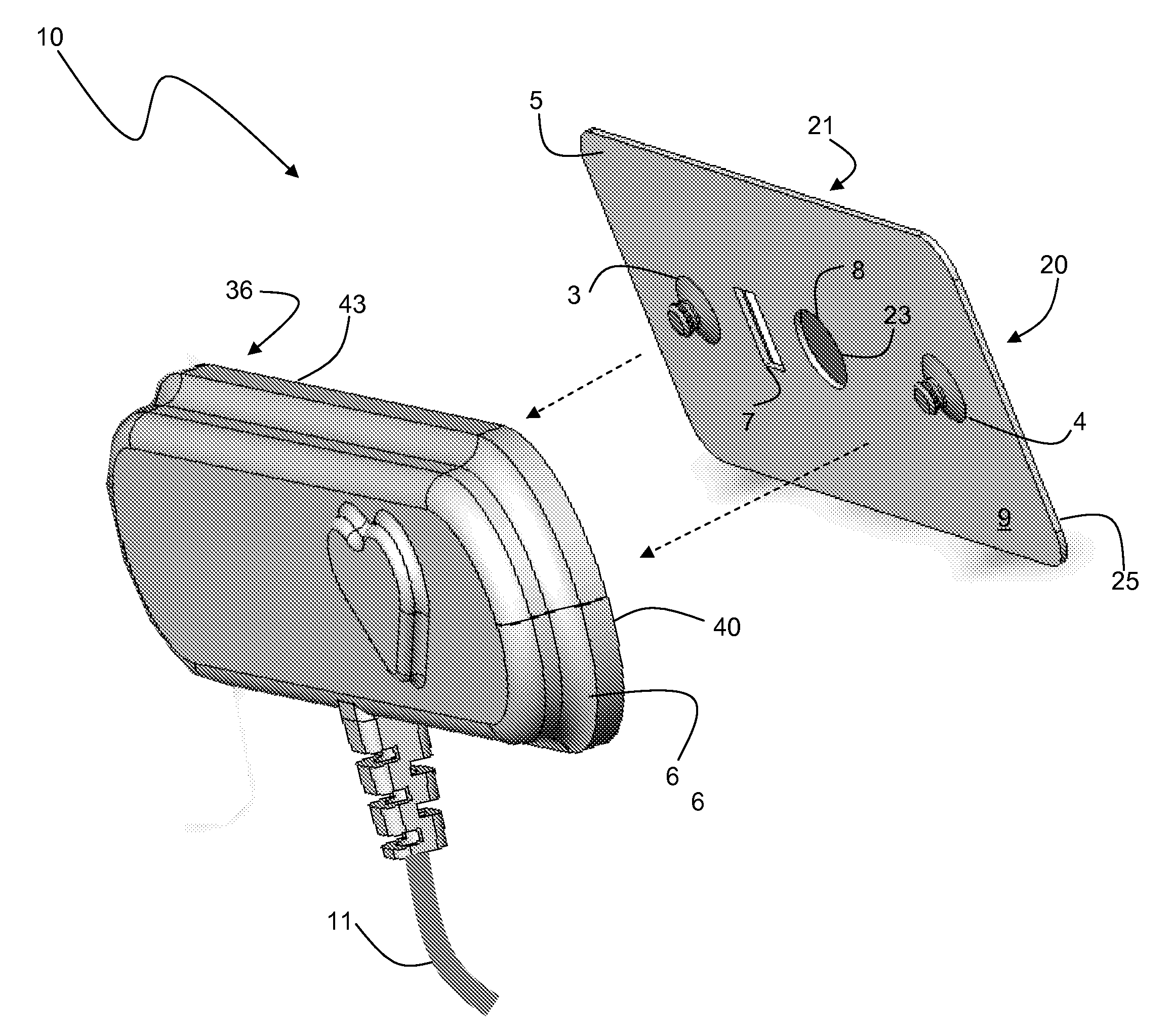
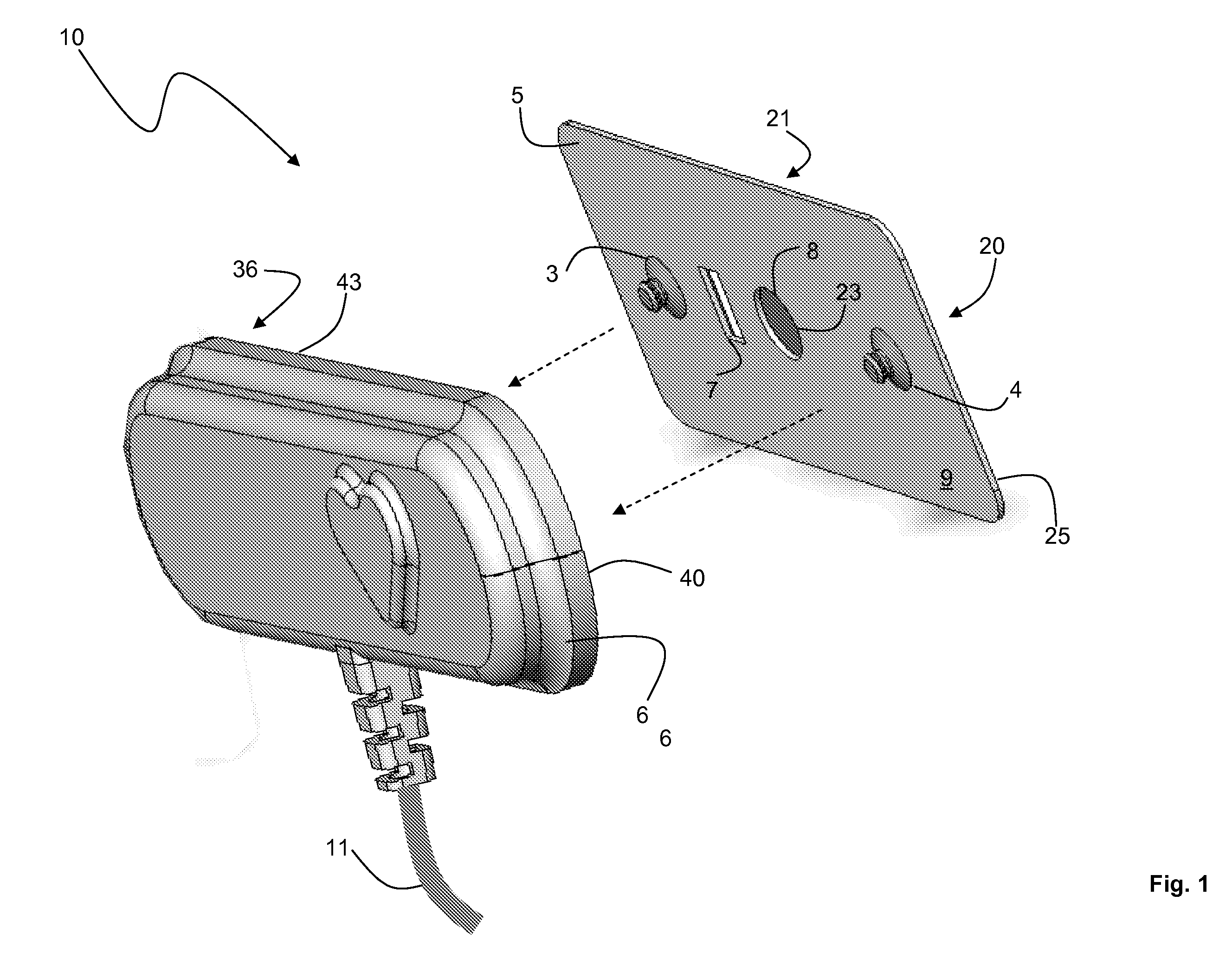
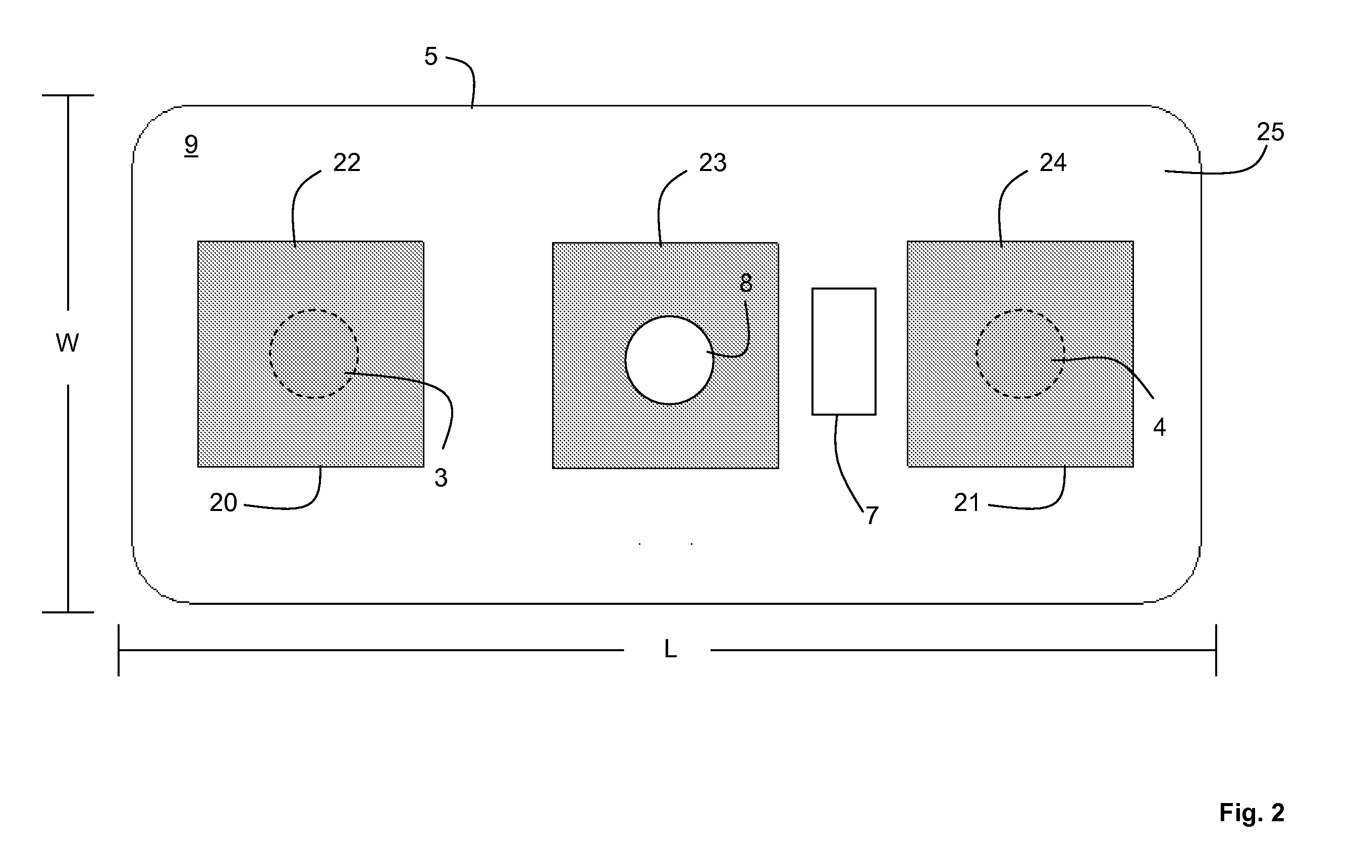
[0034]FIGS. 1, 2, and 3 show a two-part patch sensor 10 according to the invention that features a disposable adhesive patch sensor 5 that attaches to a non-disposable sensor housing 6 to measure optical, electrical, and acoustic waveforms from a patient's chest. The optical, acoustic and electrical waveforms represent, respectively, capillary blood flow, mitral and aortic valve closures, and electrical activity generated by the patient's heart. A cable 11 containing a shielded wire for each signal transports the waveforms to a main console (the components of which are shown in FIG. 8) that processes them to measure a patient's vital signs, particularly blood pressure. One such processing technique, for example, is described in detail in co-pending U.S. patent application Ser. No. 11 / 470,708, entitled Hand-Held Vital Signs Monitor, filed Sep. 7, 2006, the pertinent contents of which are hereby incorporated by reference.

[0035]The patch sensor 5 features a sterile backing 9 composed o...


PUM


Abstract

A two-component monitoring device and system for monitoring blood pressure from a patient is disclosed herein. The two-component monitoring device includes a disposable component and a main component. The disposable component features: i) a backing structure having a first aperture; and ii) first and second electrodes, each electrode connected to the backing structure and including an electrical lead and a conductive electrode material, and configured to generate an electrical signal that passes through the electrical lead when the conductive electrode material contacts the patient. The main component includes: i) first and second connectors configured to connect to the first and second electrical leads to receive the first and second electrical signals; and ii) an optical component comprising a light source that generates optical radiation and a photodetector that detects the optical radiation. The optical component inserts into the first aperture of the disposable component. The main component optionally includes an acoustic sensor. The system utilizes a processing device, connected to the monitoring device by a cable which receives and processes a plurality of signals to determine real-time blood-pressure values for the patient.

Description

CROSS REFERENCES TO RELATED APPLICATION[0001]Not ApplicableSTATEMENT REGARDING FEDERALLY SPONSORED RESEARCH OR DEVELOPMENT[0002]Not ApplicableBACKGROUND OF THE INVENTION[0003]1. Field of the Invention[0004]The present invention relates to medical devices for monitoring vital signs, e.g. blood pressure.[0005]2. Description of the Related Art[0006]Pulse transit time (‘PTT’), defined as the transit time for a pressure pulse launched by a heartbeat in a patient's arterial system, has been shown in a number of studies to correlate to both systolic and diastolic blood pressure. In these studies PTT is typically measured with a conventional vital signs monitor that includes separate modules to determine both an electrocardiogram (ECG) and pulse oximetry. During a PTT measurement, multiple electrodes typically attach to a patient's chest to determine a time-dependent ECG characterized by a sharp spike called the ‘QRS complex’. This feature indicates an initial depolarization of ventricles w...

Claims


Application Information

Patent Timeline
Patent Type & Authority Applications(United States)
IPC IPC(8): A61B5/00A61B5/04
CPCA61B5/0059A61B5/021A61B5/02125A61B5/411A61B5/6833A61B7/00A61B5/04012A61B5/04085A61B5/14551A61B5/6832A61B5/0205A61B5/68335A61B5/282A61B5/316
Inventor BANET, MATTHEW JOHNZHOU, ZHOUHUNT, KENNETH ROBERT
Owner SOTERA WIRELESS
Why Eureka
Try Eureka