Mixer For Separate-Stream Nozzle

a technology of mixer and nozzle, which is applied in the direction of propulsive elements, steering components, air transportation, etc., can solve the problems of increasing the weight of the nozzle, affecting the dynamics of the engine, and increasing the mechanical load on the flange of the nozzle exhaust casing, so as to reduce the mechanical load

Inactive Publication Date: 2008-05-22
SAFRAN CERAMICS SA
View PDF10 Cites 61 Cited by
  • Summary
  • Abstract
  • Description
  • Claims
  • Application Information

AI Technical Summary

Benefits of technology

[0005]An object of the present invention is to propose a novel design of lobe mixer for a separate-stream nozzle that serves to reduce the mechanical loads generated by the presence of such a weight at the outlet of the nozzle.

Problems solved by technology

Nevertheless, although a mixer of that type serves to improve the efficiency and the sound performance of turbojets having separate-stream nozzles, it inevitably increases the weight of the nozzle, thereby impacting the dynamics of the engine as a whole and of its connection with the wiring pylon.
Consequently, it represents a non-negligible extra weight cantilevered out from the engine, leading to an increase in the mechanical load on the flange of the nozzle exhaust casing, in particular in the event of extreme or limiting loads as occur with the loss of a blade or in response to unbalance.
This additional weight also generates an increase in the forces at the engine-to-pylon interfaces.

Method used


Image

  • Mixer For Separate-Stream Nozzle
  • Mixer For Separate-Stream Nozzle
  • Mixer For Separate-Stream Nozzle

Examples


Embodiment Construction

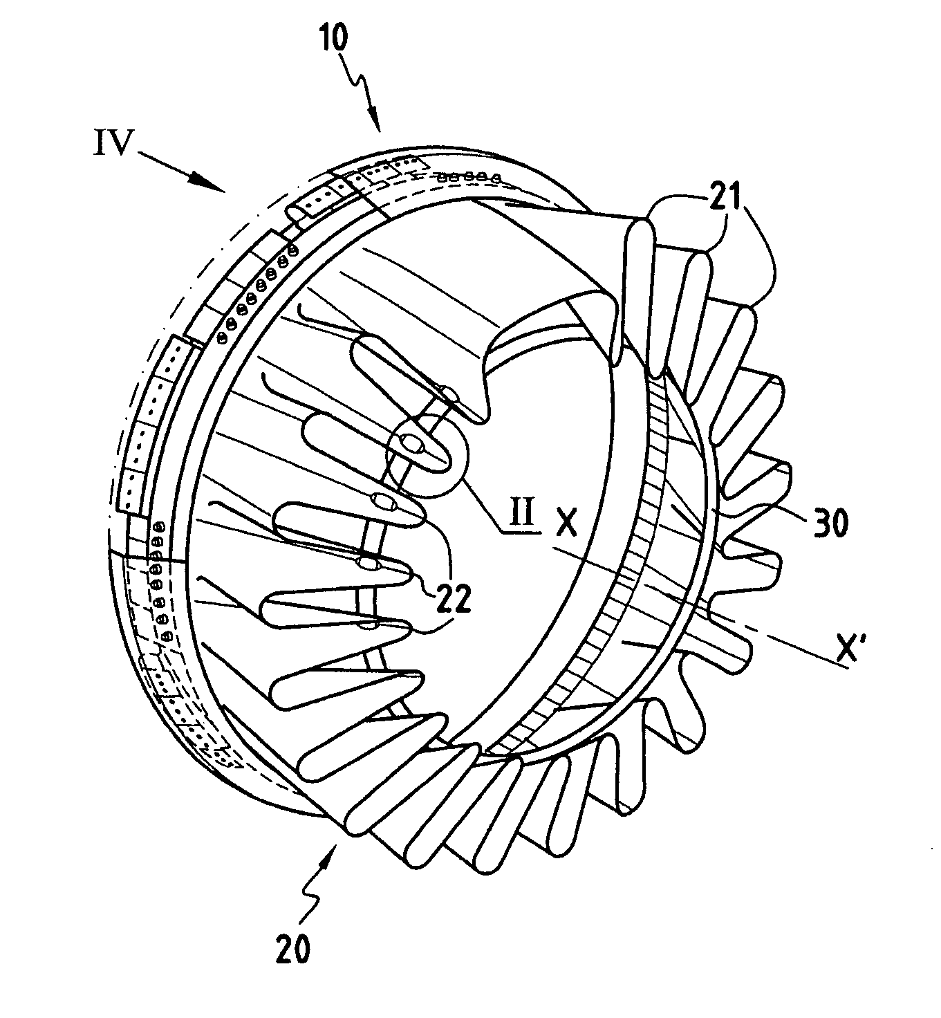
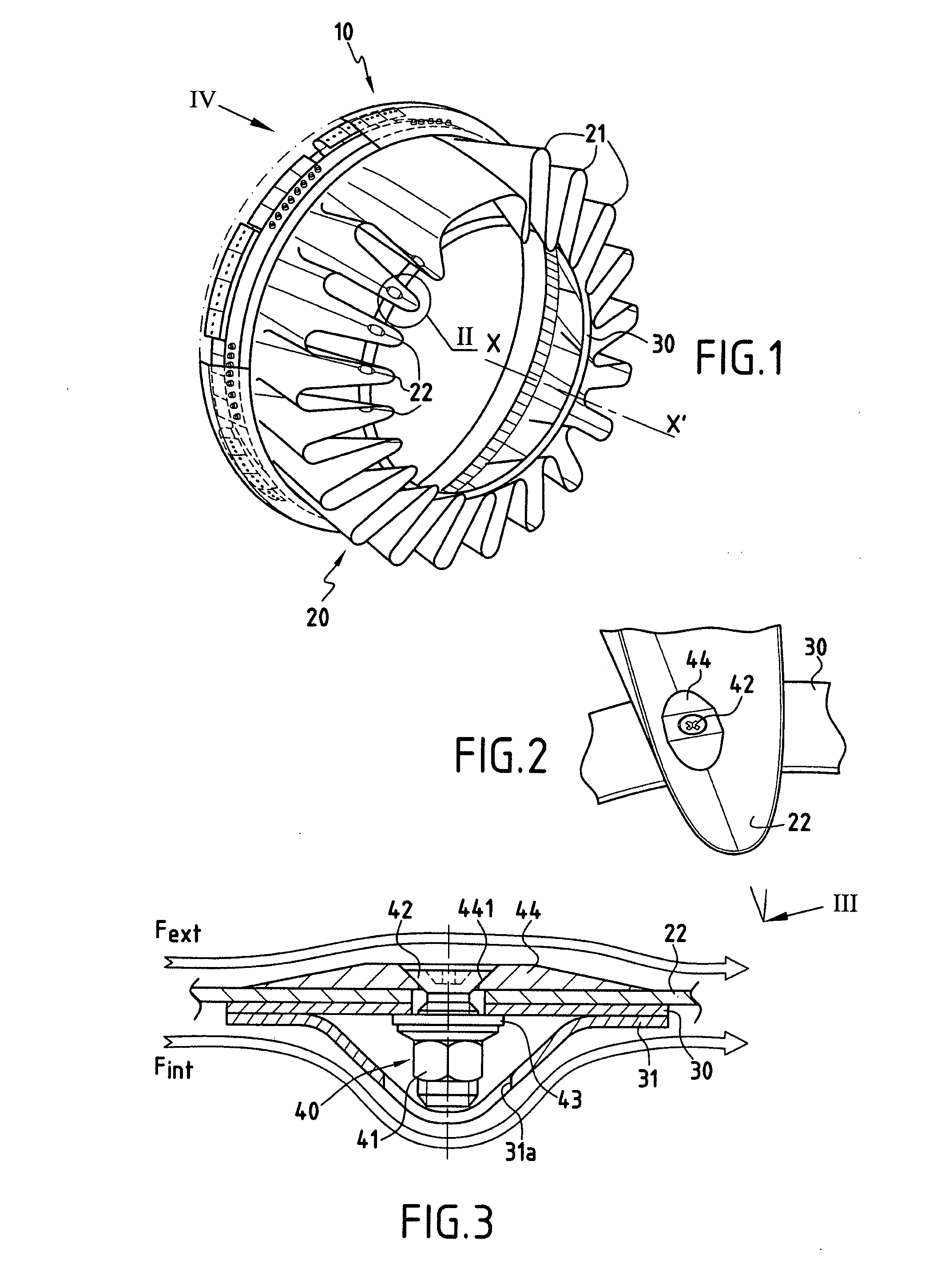
[0028]FIG. 1 shows a mixer for a separate-stream turbomachine nozzle constituting an embodiment of the invention. The mixer, which extends along a longitudinal axis X-X′, comprises firstly a fastener shroud 10 made of metal (e.g. Inconel® 625) for connecting the mixer to the exhaust casing of a turbojet nozzle (not shown), and secondly a lobe structure 20 at the end of which mixing takes place between the inner gas stream from the combustion chamber of the turbojet (also referred to as the hot stream or the primary stream) flowing inside of the mixer, and the outer stream, e.g. coming from the upstream fan (also referred to as the cold stream or the secondary stream) flowing outside the mixer.

[0029]In order to limit the noise generated at the confluence of the two streams leaving the mixer, the structure 100 presents a series of undulations forming a plurality of outer and inner lobes 21 and 22 distributed circumferentially around the longitudinal axis X-X′ of the mixer. In well kno...


PUM


Abstract

A mixer for a separate-stream turbojet nozzle, the mixer comprising along a longitudinal axis (X-X′) both a fastener shroud (10) for connecting said mixer to the exhaust casing of the nozzle, and a lobe structure (20) presenting a succession of inner and outer lobes (22 and 21) distributed circumferentially around the longitudinal axis (X-X′) of the mixer. The lobe structure (20) is made of a ceramic matrix composite material and further comprises a stiffener ring (30) that forms a connection between at least some of the lobes of said structure. Thus, the major portion of the mixer, i.e. the lobe structure, is made of a ceramic matrix composite material, thereby significantly reducing the weight of the mixer, and consequently reducing the weight of the nozzle.

Description

BACKGROUND OF THE INVENTION[0001]The present invention relates to the general field of nozzles fitted to airplane turbojets. It relates more particularly to separate-stream nozzles fitted with stream mixers that serve to reduce the noise emitted by the jet leaving the nozzle, while also improving the performance of the engine.[0002]More precisely, the separate-stream nozzles of turbojets are generally constituted by a confluent flow nacelle containing a primary cover defining a first annular channel for the flow of a primary stream (or hot stream) coming from the combustion chamber, and a secondary cover disposed concentrically around the primary cover so as to define a second annular channel for the flow of a secondary stream (or cold stream) coming from the fan.[0003]In order to reduce the noise of the jet generated at the outlet from such a nozzle, it is known to use mixers having a special design for encouraging mixing between the primary and secondary streams coming from the tu...

Claims


Application Information

Patent Timeline
Patent Type & Authority Applications(United States)
IPC IPC(8): F02K1/48F02K1/38
CPCF02K1/48F02K1/80F05D2230/642F05D2260/30Y02T50/672Y02T50/60
Inventor CONETE, ERICPHILIPPE, ERICBAROUMES, LAURENT
Owner SAFRAN CERAMICS SA
Why Eureka
Try Eureka