Clock control circuit and voltage pumping device using the same

a control circuit and voltage pumping technology, applied in process and machine control, instruments, pulse techniques, etc., can solve the problems of less than ideal voltage loss, decrement in voltage pump efficiency, etc., to achieve efficient high voltage pumping, prevent a reduction in voltage pumping efficiency, and boost the voltage level of a clock input

Active Publication Date: 2008-05-22
SK HYNIX INC
View PDF7 Cites 36 Cited by
  • Summary
  • Abstract
  • Description
  • Claims
  • Application Information

AI Technical Summary

Benefits of technology

[0013]The clock control circuit according to the present disclosure and the voltage pumping device using the clock control circuit can greatly boost the voltage level of a clock input to the voltage pump, for voltage pumping. Accordingly, it is possible to efficiently pump the high voltage and back-bias voltage while preventing a reduction in voltage pumping efficiency caused by a voltage loss corresponding to the threshold voltage of a MOS transistor used as a switch.
[0014]The clock control circuit according to the present disclosure performs an operation for increasing the swing width of the clock input to the clock control circuit. That is, the clock control circuit boosts the voltage level of the clock. In one aspect, the present disclosure provides a circuit for generating an output clock having the same phase as an input clock. In another aspect, the present disclosure provides a circuit for generating an output clock having a phase opposite to that of an input clock.
[0015]In the clock control circuit of the present disclosure, a clock having an increased voltage level is input to the voltage pump of the voltage pumping device, as a clock signal for pumping a high voltage or a back-bias voltage. Since the voltage pump of the present disclosure is operated in accordance with the clock having an increased voltage level, it is possible to efficiently pump the high voltage and back-bias voltage while preventing a reduction in voltage pumping efficiency caused by a voltage loss corresponding to the threshold voltage of a MOS transistor used as a switch.

Problems solved by technology

In this case, however, a voltage loss corresponding to the threshold voltage is generated due to the characteristics of the MOS transistor, thereby causing a degradation in the efficiency of the voltage pump.
For this reason, when the supply voltage is lowered, it is more difficult to overcome the voltage loss corresponding to the threshold voltage and to pump each of the high voltage VPP and back-bias voltage VBB to a desired level.

Method used


Image

  • Clock control circuit and voltage pumping device using the same
  • Clock control circuit and voltage pumping device using the same
  • Clock control circuit and voltage pumping device using the same

Examples


first embodiment

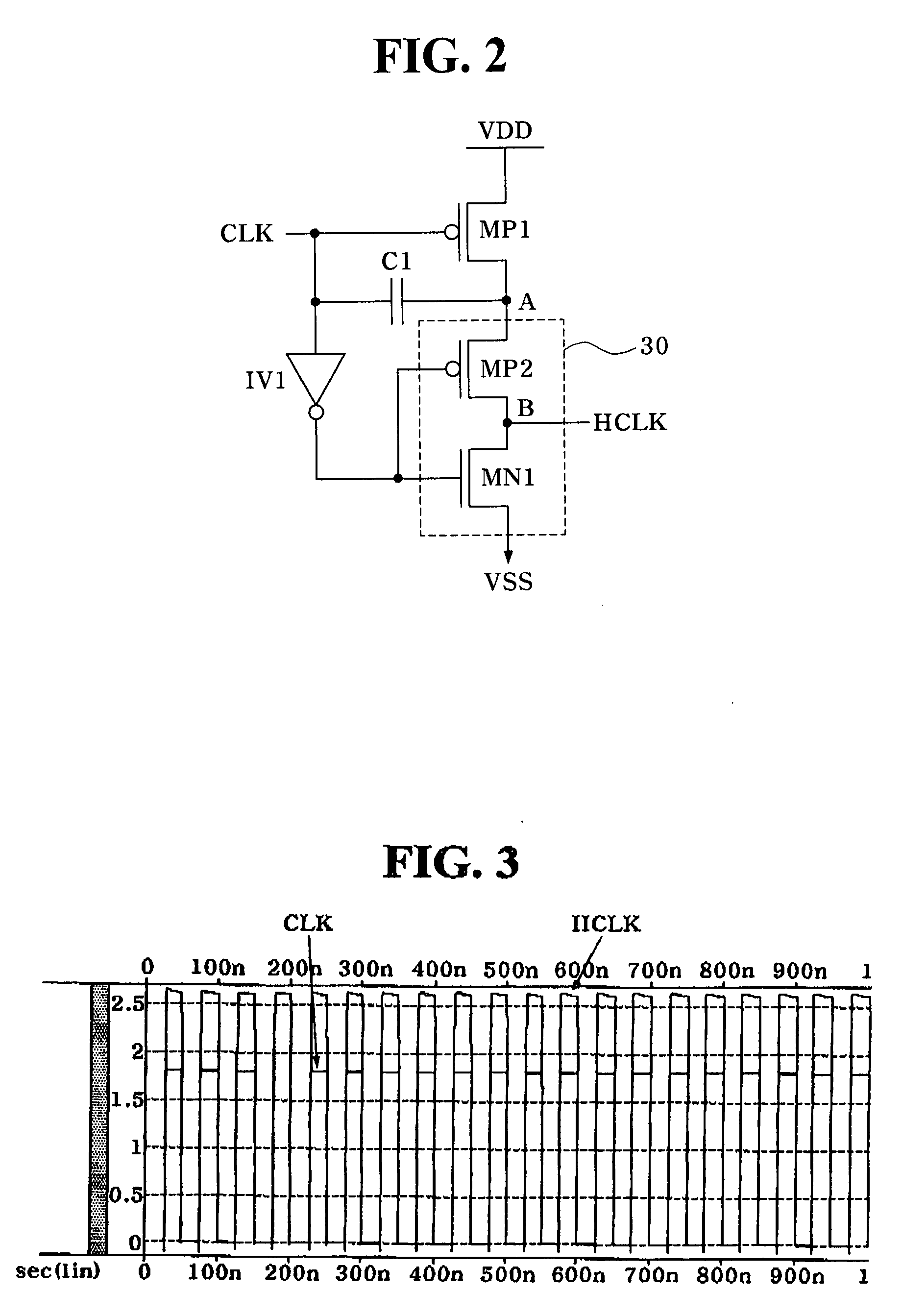
[0027]FIG. 2 is a circuit diagram illustrating the clock controller 3. FIG. 3 is a waveform diagram illustrating input and output clocks of the clock controller shown in FIG. 2.

[0028]As shown in FIG. 2, the clock controller 3 according to the first embodiment of the present disclosure includes a PMOS transistor MP1 connected between an input terminal for a supply voltage VDD (hereinafter, this terminal will be referred to as a “supply voltage terminal VDD”), and a node A, and configured to supply the supply voltage VDD to the node A in response to the first clock signal CLK. The first clock signal CLK has a swing width of VDD, namely, a swing width corresponding to a voltage range of 0 to VDD. The clock controller 3 also includes a capacitor C1 connected between an input terminal for the first clock signal CL and the node A, and configured to boost the voltage level of the node A to the level of the supply voltage VDD in response to the first clock signal CLK, and a clock generator ...

second embodiment

[0034]FIG. 4 is a circuit diagram illustrating the clock controller 3. FIG. 5 is a waveform diagram illustrating input and output clocks of the clock controller shown in FIG. 4.

[0035]As shown in FIG. 4, the clock controller 3 according to the second embodiment of the present disclosure includes an inverter IV2 connected to the supply voltage terminal VDD and a node C, and configured to buffer the first clock signal CLK which has a swing width of VDD, namely, a swing width corresponding to a voltage range of 0 to VDD. The clock controller 3 also includes a PMOS transistor MP3 configured to supply the supply voltage VDD to the node C in response to an output signal from the inverter IV2, and a capacitor C2 connected between an output terminal of the inverter IV2 and the node C, and configured to boost the voltage level of the node C to the level of the supply voltage VDD in response to the output signal from the inverter IV2. The clock controller 3 further includes a clock generator 3...


PUM


Abstract

A clock control circuit is provided. The clock control circuit includes a voltage supplier for supplying a first voltage in response to a first clock signal, a voltage booster for boosting the first voltage in response to the first clock signal input to the voltage booster, and a clock generator for generating a second clock signal having a voltage level equal to the boosted first voltage in response to the first clock signal.

Description

BACKGROUND[0001]The present disclosure relates to a clock control circuit and a voltage pumping device using the same, and more particularly to a clock control circuit and a voltage pumping device using the same which are capable of achieving an enhancement in pumping efficiency.[0002]Generally, a DRAM is a random access memory capable of writing or reading data to / from memory cells each consisting of one transistor and one capacitor. Since such a DRAM uses an NMOS transistor for the transistor of each memory cell, it also includes a voltage pumping device for driving word lines, taking into consideration a voltage loss caused by a threshold voltage Vt, in order to generate a voltage higher than a sum of an external supply voltage Vdd and the threshold voltage Vt (Vdd+Vt).[0003]That is, in order to turn on the NMOS transistor mainly used for each DRAM memory cell, it is necessary to apply, to the gate of the NMOS transistor, a voltage higher than a source voltage by the threshold vo...

Claims


Application Information

Patent Timeline
Patent Type & Authority Applications(United States)
IPC IPC(8): G05F3/02
CPCH02M2003/076H02M3/07H02M3/076G11C5/145G11C7/222G11C11/4074G11C11/4076
Inventor JUNG, JONG HO
Owner SK HYNIX INC
Why Eureka
Try Eureka