Log-Periodic Dipole Array (LPDA) Antenna and Method of Making

a dipole array and dipole array technology, applied in the direction of antennas, non-resonant long antennas, electrically long antennas, etc., can solve the problems of many traditional lpda designs incorporating these techniques, few traditional lpda designs, and intermittent electrical conta

Inactive Publication Date: 2008-05-22
TDK CORPARATION
View PDF10 Cites 13 Cited by
  • Summary
  • Abstract
  • Description
  • Claims
  • Application Information

AI Technical Summary

Problems solved by technology

However, soldering and welding are seldom used, because the intense localized heating required by these processes tends to distort the antenna structure.
However, traditional LPDA designs incorporating these techniques still present many disadvantages.
For example, conventional LPDA antennas that use screws (or other mechanical fasteners) to attach the dipole elements to the feed conductors often suffer from intermittent electrical contact at the base of the elements (i.e., at the connection points between the dipole elements and the feed conductors).
This leads to unavoidable oxidation and intermittent electrical contact at the base of the elements.
However, soldering and welding require intense localized heating, which tends to distort the antenna structure.
In addition, LPDA designs employing dipole elements attached with mechanical fasteners become impractical at high operating frequencies (e.g., at about microwave frequencies and above).
Thus, it becomes very expensive to extend the high frequency limit of a traditional LPDA antenna into the microwave frequency range.
In addition, the over / under feed mechanism necessarily staggers the two halves of each dipole to accommodate higher frequency limits.
However, staggering introduces cross-polarized radiated fields, which can only be minimized by reducing the size of the feed geometry.
This often results in power handling problems and increases the difficulty of assembly.
Even though LPDA antennas built using printed circuit technology enable high frequency operation, they provide their own set of disadvantages.
Even these substrates cause a significant perturbation of the electromagnetic field, which ultimately degrades the intended radiation pattern.
In addition, printed circuit antennas are typically limited to operating over a narrow, high frequency range and not readily or inexpensively adapted for operating over relatively larger frequency ranges.
However, the marriage of two dissimilar LPDAs (i.e., the presence of dielectric in the printed circuit based LPDA and the absence of dielectric in the traditional LPDA necessarily makes them dissimilar) inevitably results in some performance degradation, especially in the cross-over region (i.e., the region arranged about the upper frequency limit of the traditional LPDA and the lower frequency limit of the printed circuit LPDA).
The presence of a dielectric substrate also tends to degrade the frequency independent nature of the LPDA antenna.

Method used


Image

  • Log-Periodic Dipole Array (LPDA) Antenna and Method of Making
  • Log-Periodic Dipole Array (LPDA) Antenna and Method of Making
  • Log-Periodic Dipole Array (LPDA) Antenna and Method of Making

Examples


Embodiment Construction

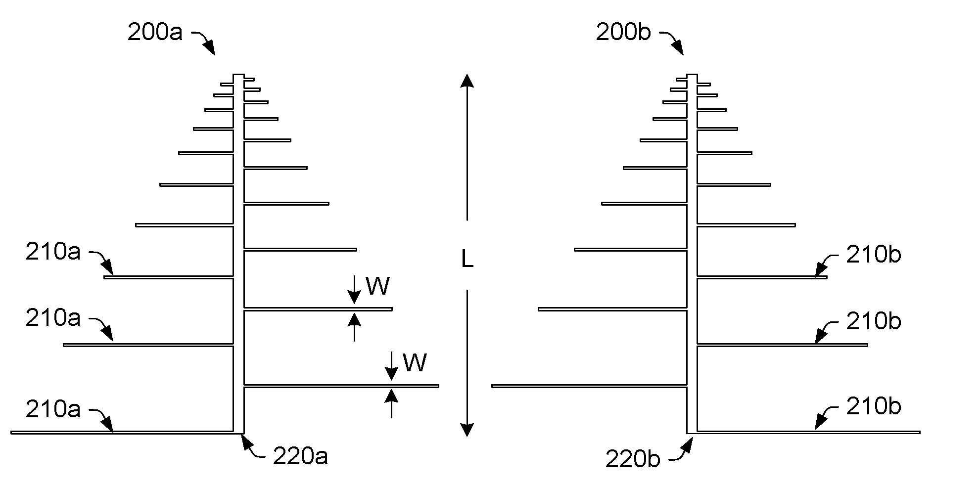
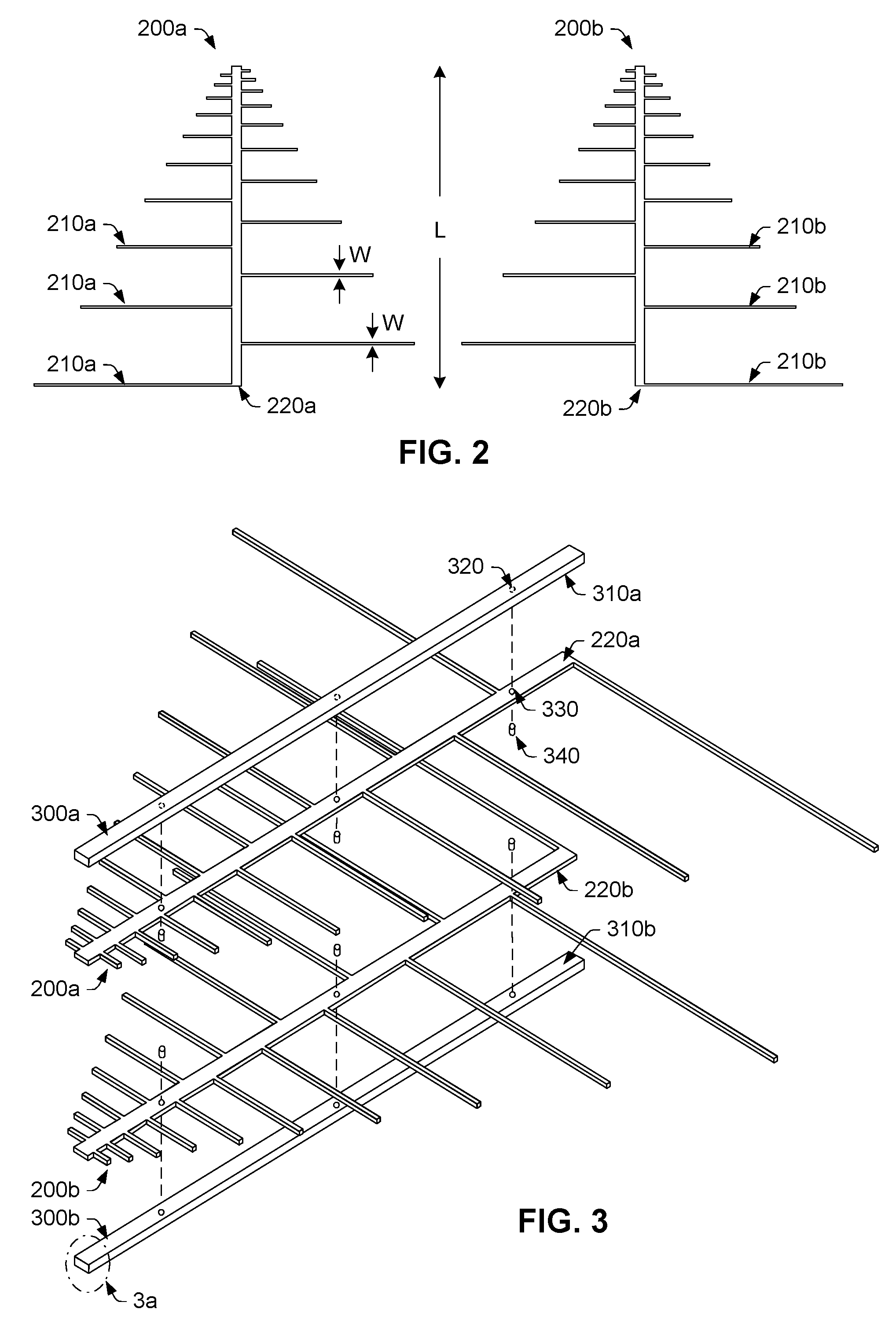
[0043]Turning now to the drawings, FIGS. 1-11 illustrate various embodiments of an improved LPDA antenna and method of making. As described in more detail below, the improved LPDA antenna overcomes numerous problems associated with both traditional and printed circuit LPDA designs. For example, the improved LPDA antenna provides a high frequency alternative to both traditional and printed circuit LPDA designs. Second, the improved LPDA antenna improves upon traditional LPDA designs by eliminating the electrical contact problem associated with thermal expansion / oxidation of the mechanical fasteners used to connect the dipole elements to the feed conductors. Third, the improved LPDA antenna improves upon printed circuit LPDA designs by eliminating the pattern disturbances associated with a dielectric substrate. Other improvements / advantages may become apparent in light of the description below.

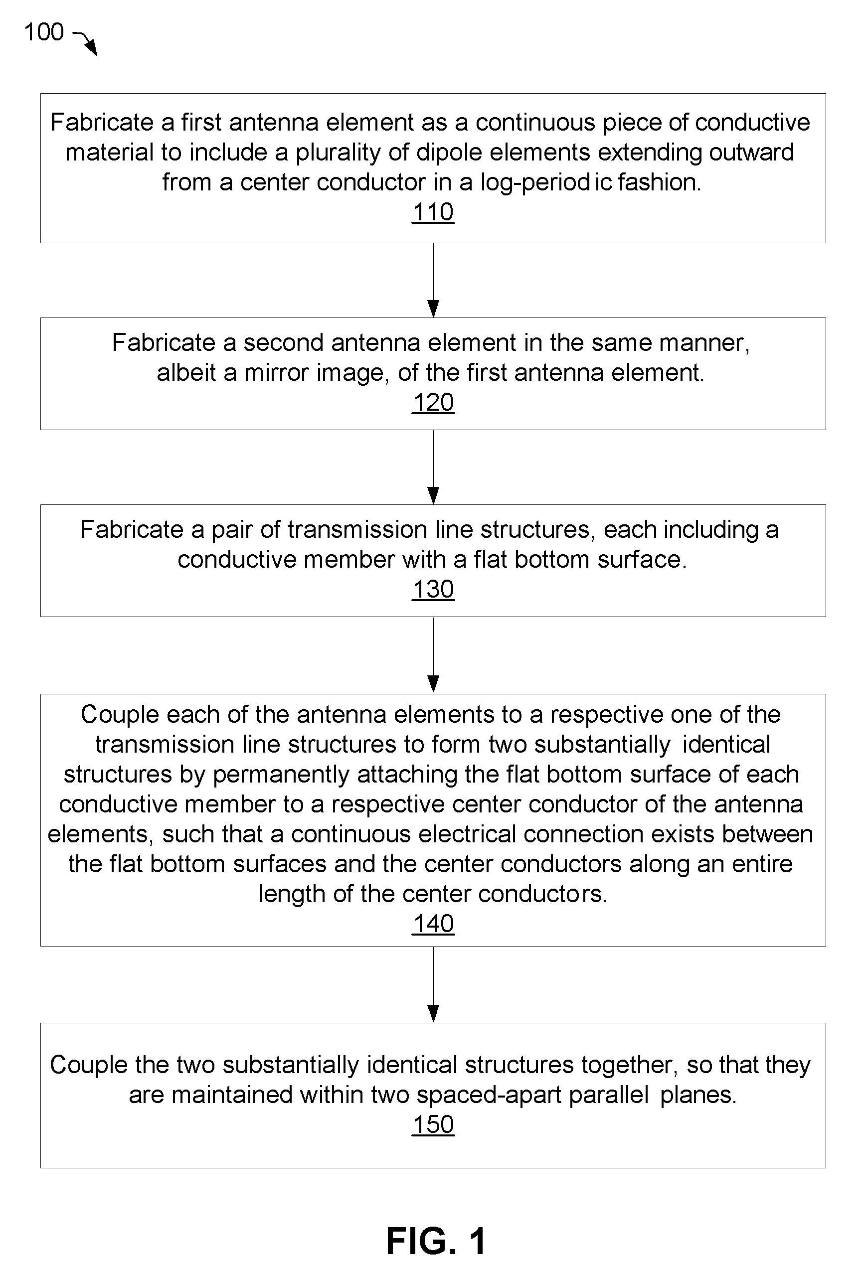
[0044]FIG. 1 illustrates an improved method (100) for making a log periodic dipole array (LP...


PUM

PropertyMeasurementUnit
relative permittivityaaaaaaaaaa
frequencyaaaaaaaaaa
frequencyaaaaaaaaaa

Abstract

A log periodic dipole array (LPDA) antenna including a first antenna element, a second antenna element and a pair of transmission line structures is provided herein. The first antenna element is fabricated as a continuous piece of conductive material to include a plurality of dipole elements extending outward from a center conductor. The second antenna element is fabricated in the same manner, albeit a mirror image, of the first antenna element. In one embodiment, the antenna elements are fabricated by cutting a contour of the plurality of dipole elements and the center conductor from a sheet of metal (e.g., aluminum or one of its alloys). The antenna elements and transmission line structures are preferably coupled, such that no electrical discontinuities exist between the antenna elements and a respective transmission line structure. In one embodiment, a conductive epoxy or a brazing process is used to permanently attach flat bottom surfaces of the transmission line structures to a different center conductor of the first and second antenna elements.

Description

BACKGROUND OF THE INVENTION[0001]1. Field of the Invention[0002]This invention relates to broadband antenna design and, more particularly, to a log-periodic dipole array (LPDA) antenna with improved performance over a broad frequency range.[0003]2. Description of the Related Art[0004]The following descriptions and examples are given as background only.[0005]Log-periodic dipole array (LPDA) antennas are popular broadband antennas for many applications. In general, an LPDA antenna includes a collection of linear or tapered dipoles, which are scaled and arranged in a log-periodic array. Each dipole within the array comprises two elements or halves, which vary in length and extend outward from a pair of transmission line structures (i.e., “feed conductors”). The dipoles are arranged from shortest to longest, such that the length and spacing between dipole elements varies logarithmically along the antenna. In addition, the dipole lengths and spacings are related to the frequency range ov...

Claims


Application Information

Patent Timeline
Patent Type & Authority Applications(United States)
IPC IPC(8): H01Q11/10H01P11/00
CPCY10T29/49016H01Q11/10
Inventor MCLEAN, JAMES S.
Owner TDK CORPARATION
Why Eureka
Try Eureka