Communication system and communication apparatus

Inactive Publication Date: 2008-05-22
SONY CORP
View PDF26 Cites 46 Cited by
  • Summary
  • Abstract
  • Description
  • Claims
  • Application Information

AI Technical Summary

Benefits of technology

[0044]According to an embodiment of the present invention, there is provided the superior communication system, as well as the superior communication apparatus, which realizes the efficient transmission of the RF signals between the EFC antennas respectively included in the information apparatuses arranged in the ultra-close range, thereby enabling the large capacity transmission by use of the induction field a

Problems solved by technology

However, since radio communication by use of the antenna emits radio waves from a transmitting side, regardless of whether there exist the other party for making communication or not, a problem exists in that a source of radio disturbance against communication systems which are arranged in close range each other is caused.
Further, the antenna also receives radio waves inclusive of those transmitted from a distant place, and hence, is easily affected by disturbing radio waves around, whereby reception sensitivity is degraded.
Further, a change of polarized wave direction to an orthogonal direction results in a failure of the radio waves communication.
The radio communication by use of the radiant electromagnetic field encounters a difficulty in realizing high-speed large-capacity feeble radio communication, because the electric field strength is inversely proportional to a distance and attenuation of the electric field strength due to the distance is relatively small.
The related art communication based on the capacitive coupling is unsuitable for transmission of a large capacity of data because low frequency signals are used.
Hereupon, in the communication by use of high frequencies covering GHz-bands, like the UWB

Method used


Image

  • Communication system and communication apparatus
  • Communication system and communication apparatus
  • Communication system and communication apparatus

Examples


Example

[0065]Embodiments of the present invention are hereinafter described with reference to the accompanying drawings.

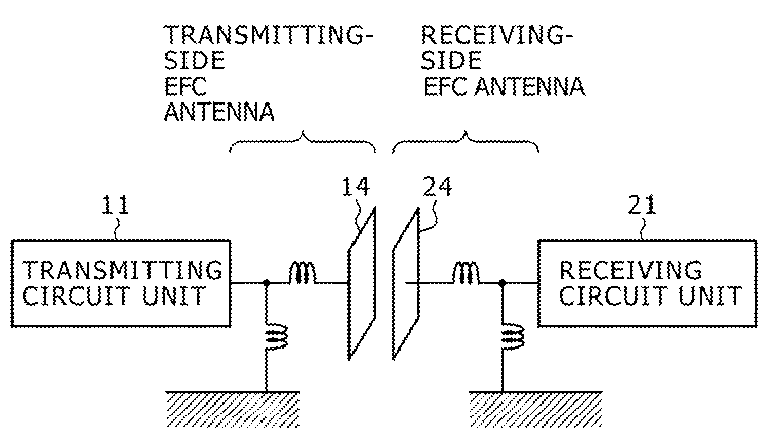
[0066]An embodiment of the present invention relates to a communication system adapted to perform data transmission between information apparatuses by use of an induction field and / or an electrostatic field. According to a communication system based on capacitive coupling, no coupling relation is created in the absence of the other party for making communication in a close range and radio waves are not radiated, causing no interference with other communication systems. Even if the radio waves are transmitted from a distant place, an EFC antenna makes no radio wave reception, resulting in exemption from interference by the other communication systems.

[0067]In the related art radio communication by use of an antenna, the field strength of a radiant electromagnetic field attenuates by amounts which are inversely proportional to a distance. In contrast to the above, an induct...


PUM


Abstract

A communication system, including a transmitter having a transmitting circuit unit to generate a data transmission-adaptive RF signal and an electric-field-coupling antenna to send out the RF signal as an induction field and/or an electrostatic field, a receiver having a electric-field-coupling antenna and a receiving circuit unit to receive and process the RF signal received by the electric-field-coupling antenna, and a coupling apparatus having a plurality of transmitter-side electric-field-coupling antennas to receive the RF signal which is in capacitive coupling with the transmitter-side electric-field-coupling antenna and outputted from the electric-field-coupling antenna, a signal line to transmit the received RF signal, and a plurality of receiver-side electric-field-coupling antennas to output the RF signal which is in capacitive coupling with said the receiver-side electric-field-coupling antenna and transmitted through the signal line.

Description

BACKGROUND OF THE INVENTION[0001]1. Field of the Invention[0002]The present invention relates to a communication system, as well as to a communication apparatus, which is adapted to perform large capacity data communication among information apparatuses, and particularly, relates to a communication system, as well as to a communication apparatus, which is adapted to perform data communication among information apparatuses by use of an electrostatic field without causing interference with other communication systems.[0003]More specifically, an embodiment of the present invention relates to a communication system, as well as to a communication apparatus for transmitting radio frequency (herein after referred to as RF) communication signal between information apparatuses each of which is spaced apart in an ultra-close range, by use of an electrostatic field and / or an induction field, and more particularly, to a communication system, as well as to a communication apparatus, which allows...

Claims


Application Information

Patent Timeline
IPC IPC(8): H04B5/00
CPCH04B5/0012H04B5/0081H04B5/0018
Inventor WASHIRO, TAKANORI
Owner SONY CORP
Why Eureka
Try Eureka