Absolute steering angle detecting device

a detection device and absolute steering angle technology, applied in the direction of steering initiation, instruments, vessel construction, etc., can solve the problems of resolution problem, linearity being worsened double, and unresolved problem

Inactive Publication Date: 2008-05-22
NSK LTD
View PDF0 Cites 32 Cited by
  • Summary
  • Abstract
  • Description
  • Claims
  • Application Information

AI Technical Summary

Benefits of technology

[0006]The present invention has been made in view of the unsolved problem inherent in the conventional example, and an object thereof is to provide an absolute steering angle detecting device which can detect an absolute steering angle quickly while maintaining the resolution and linearity provided by the one-rotation steering angle detecting system by detecting an absolute steering angle of one period through one rotation of a steering wheel.

Problems solved by technology

Consequently, although the detection speed of absolute steering angle can be made fast, since the steering angle per rotation becomes double that of a one-rotation steering angle detecting system in which a steering angle of one period is made to be obtained by one rotation of a steering wheel, there still remains an unsolved problem of resolution and linearity being worsened double when compared with the one-rotation steering angle detecting system.

Method used


Image

  • Absolute steering angle detecting device
  • Absolute steering angle detecting device
  • Absolute steering angle detecting device

Examples


first embodiment

[0179]Note that while in the first embodiment, the invention has been described as being applied to the rear-drive vehicle, the invention is not limited thereto. The present invention may be applied to a front-drive vehicle in such a way that a first estimated steering angle is calculated based on wheel speeds of rear wheels which constitute driven wheels, while a second estimated steering angle is calculated based on wheel speeds of front wheels which constitute driving wheels.

second embodiment

[0180]Next, the invention will be described by reference to FIGS. 10 to 14.

[0181]This second embodiment is such that an initial steering angle is set based on a self-aligning torque SAT and a vehicle speed Vs in place of the configuration of the first embodiment described above in which the initial absolute steering angle is estimated based on the wheel speeds.

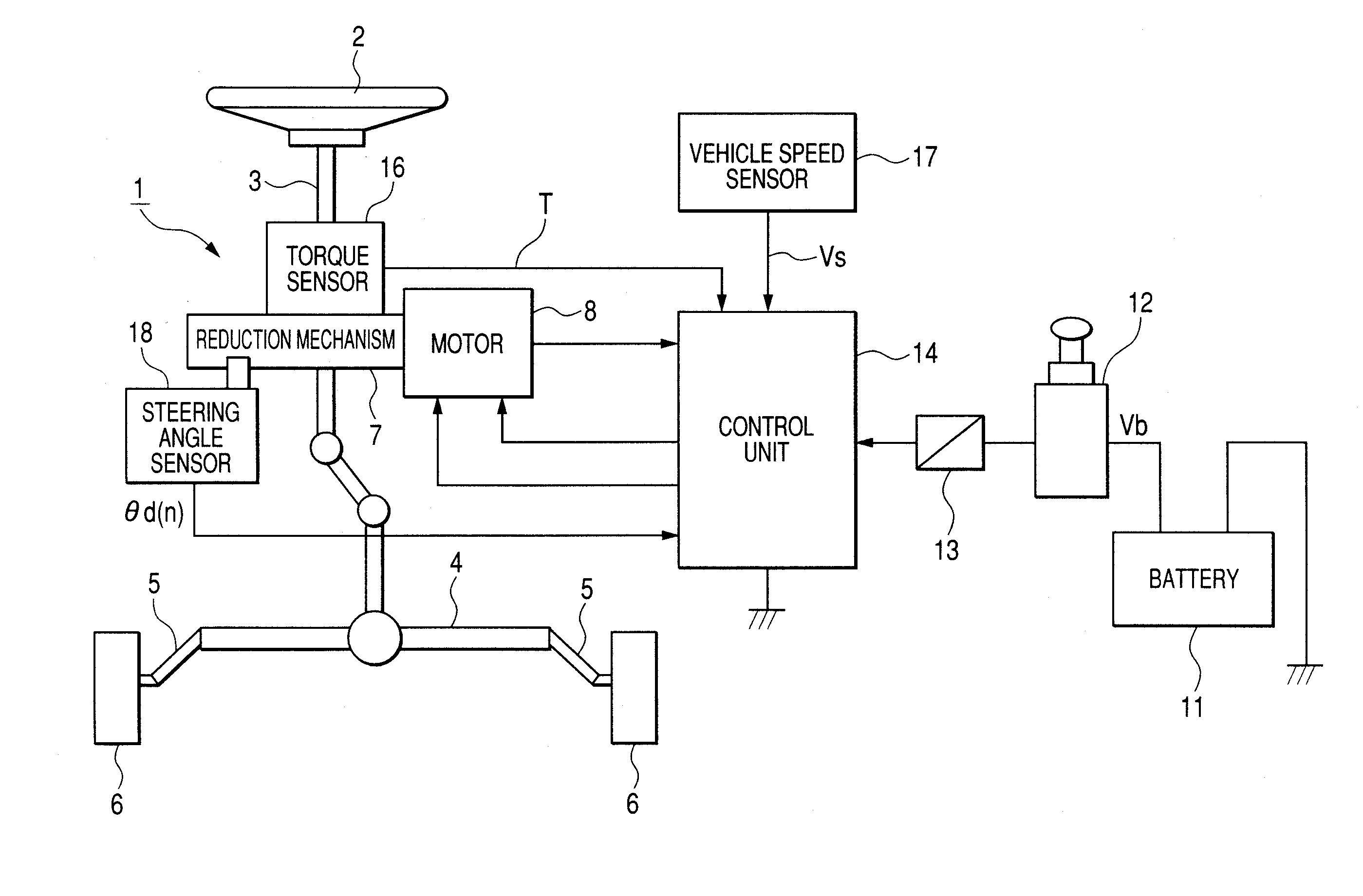
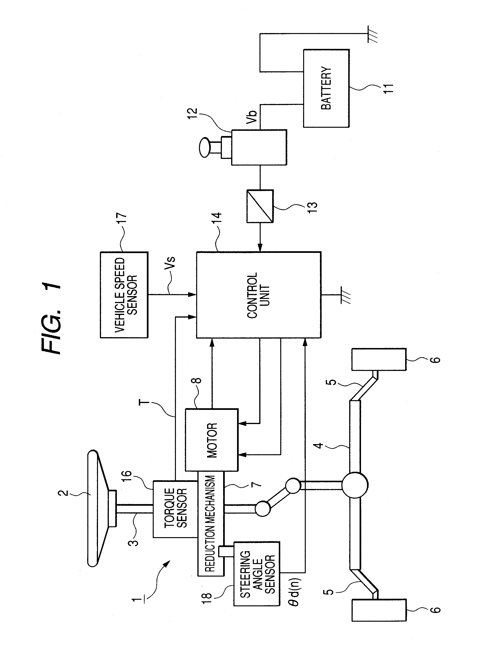
[0182]Namely, the second embodiment has a similar configuration to that shown in FIG. 5 except for a configuration in which a self-aligning torque estimation module 40 is provided in a control unit 14 which detects a self-aligning torque SAT which acts on the vehicle and the self-aligning torque SAT detected by this self-aligning torque estimation module 40 and a vehicle speed Vs detected by a vehicle speed sensor 17 are made to be supplied to an absolute steering angle calculation module 26, and hence, like reference numerals will be imparted to like constituent components to those shown in FIG. 5, and the detailed descriptio...

third embodiment

[0206]Nest, the invention will be described by reference to FIGS. 15 to 17.

[0207]This third embodiment is such that in the initial turn number determining operation in the first embodiment, the determination of the initial turn number is made to be implemented faster than in the first embodiment by utilizing the final absolute steering angle resulting when the immediately preceding driving was completed.

[0208]Namely, as is shown in FIG. 15, the third embodiment has a similar configuration to that shown in FIG. 5 except for a configuration in which the final absolute steering angle θe in the immediately preceding driving is made to be stored in a non-volatile memory 24. The final absolute steering angle θe is read when an ignition switch is put in an on state by an absolute steering angle calculation module 26, so as to execute the initial turn number determining operation.

[0209]Then, an absolute steering angle storing operation shown in FIG. 16 is executed by the absolute steering a...


PUM


Abstract

There is provided an absolute steering angle detecting device for detecting an absolute steering angle of a steering control device of a vehicle, including a sensor wheel 18c adapted to rotate by linking with rotation of the steering control device, a magnetism detector 18g having a bridge circuit made up of a GMR element, magnetized portions 18d, 18e provided to surround the magnetism detector 18g, and a steering angle operation module 26 which calculates an absolute steering angle based a detection signal outputted from the magnetism detector 18g, wherein either the magnetism detector 18g or the magnetized portions 18d, 18e is mounted on the sensor wheel 18c, while the other is mounted on a fixed portion, and the magnetism detector 18g outputs a detection signal which completes a single period when the steering control device completes a single rotation.

Description

TECHNICAL FIELD[0001]The present invention relates to an absolute steering angle detecting device for detecting an absolute steering angle of a steering control device (such as a steering wheel) of a vehicle.BACKGROUND ART[0002]As an absolute steering angle detecting device of this type, there is, for example, an absolute steering angle detecting device which was proposed previously by the applicant of this subject patent application and which is described in Japanese Patent Unexamined Publication No. JP-A-2005-91137.[0003]The conventional example described in JP-A-2005-91137 is a steering angle sensor adapted to calculate a rotational angle of a steering wheel by detecting a rotational angle of a steering system in which a steering assist is implemented via a reduction mechanism by driving an electric motor. In the conventional example, there is provided a sensor wheel adapted to operate while linking with rotation of a steering shaft; an absolute angle operation unit which calcula...

Claims


Application Information

Patent Timeline
Patent Type & Authority Applications(United States)
IPC IPC(8): B62D15/00
CPCB62D15/0245G01D5/145G01D5/04G01D2205/26
Inventor WEI, YONGHARA, TAKESHI
Owner NSK LTD
Why Eureka
Try Eureka