
Electronic package evaluation apparatus, electronic package optimizing apparatus, and computer-readable recording medium in which electronic package evaluation program is recorded

Inactive Publication Date: 2008-05-29
FUJITSU LTD
View PDF4 Cites 8 Cited by
  • Summary
  • Abstract
  • Description
  • Claims
  • Application Information

AI Technical Summary

Benefits of technology

[0032]In this manner, with this invention, when the whole analysis model creating unit creates the first mesh data for use in the outline analysis of the whole electronic package, as to the solder connection parts of the electronic package, a solder connection part model is created having the volume, height, and connection area as the same as the volume, height, and connection area of the solder connection part. Since this solder connection part model is divided into multiple meshes, while decreasing the time required for the whole analysis by the whole analysis executing unit, it is possible to accurately analyze with respect to the solder connection parts.
[0033]Further, the target solder connection part extracting unit extracts a target solder connection part based on the analysis result obtained by the whole analysis executing unit, and the detail analysis unit performs more accurate analysis than an analysis by the hole analysis executing unit to the target solder connection part to perform evaluation of the reliability of the electronic package. Thus, highly accurate analysis is performed to the electronic package, so that accurate evaluation with respect to the electronic package can be performed.

Problems solved by technology

Here, in electronic packages (in particular, BGA and CSP in which components are densely mounted), if load is generated due to temperature change or fall impactive force, it often occurs that the largest distortion and force are generated in solder connection parts of the components of the electronic packages.
Thus, it is impossible to accurately evaluate a solder connection parts.

Method used


Image

  • Electronic package evaluation apparatus, electronic package optimizing apparatus, and computer-readable recording medium in which electronic package evaluation program is recorded
  • Electronic package evaluation apparatus, electronic package optimizing apparatus, and computer-readable recording medium in which electronic package evaluation program is recorded
  • Electronic package evaluation apparatus, electronic package optimizing apparatus, and computer-readable recording medium in which electronic package evaluation program is recorded

Examples


Embodiment Construction

[0049]Embodiments of the present invention will now be described with reference to the relevant accompanying drawings.

[1] One Preferred Embodiment

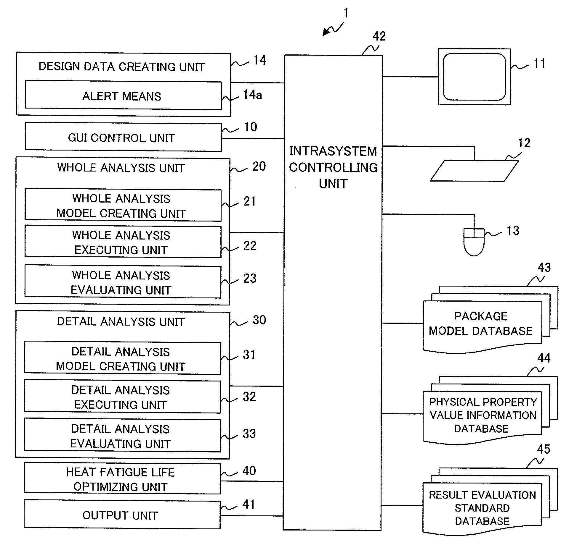
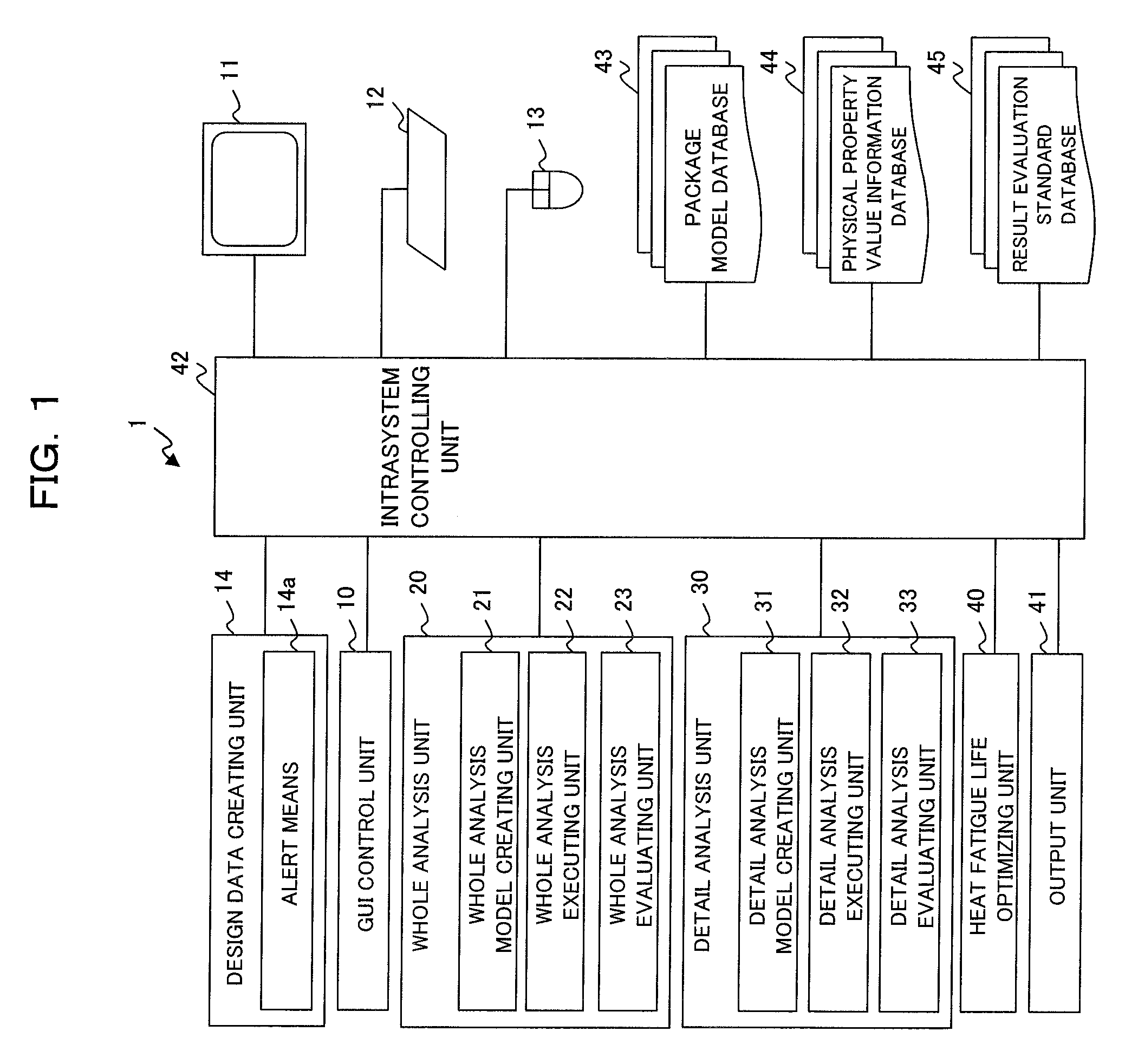
[0050]First of all, a description will be made of an electronic package optimizing apparatus according to one preferred embodiment of the present invention. FIG. 1 is a block diagram which shows a construction of an electronic package optimizing apparatus according to one preferred embodiment of the present invention.

[0051]As shown in FIG. 1, the electronic package optimizing apparatus 1 includes: a GUI (Graphical User Interface) control unit 10, a monitor (display unit) 11, a key board 12, a mouse 13, a design data creating unit 14, a whole analysis unit 20, a detail analysis unit 30, a heat fatigue life optimizing unit (life cycle optimizing unit) 40, an output unit 41, an intrasystem controlling unit 42, a package model database (package model holding unit) 43, a physical value information database (material information holding unit) 44...


PUM


Abstract

When reliability evaluation of the whole electronic package is performed, the time required for simulation is decreased, while solder connection parts, in particular, are accurately analyzed. The whole analysis model creating unit creates a solder connection part model which has the same volume, height, and connection area as the volume, height, and connection area of the solder connection part. By means of dividing the solder connection model into multiple meshes, the first mesh data for use in electronic package analysis is created.

Description

TECHNICAL FIELD[0001]The present invention relates to technology for evaluating electronic package reliability. In particular, the invention relates to technology for creating mesh data for used in construction analysis of the electronic package.BACKGROUND ART[0002]Recently, electronic equipment such as personal computers and mobile telephones is highly integrated and greater packaging density is realized, and pitch fine design of an electronic package which is mounted for such electronic equipment has been developed at the same time. As the integration and downsizing of the electronic package proceed, concerns about reliability of packaging components, in particular, a solder connection part are increased.[0003]Generally speaking, when a high density packaging is required for an electronic packaging, BGA (Ball Grid Array) or CSP (Chip Scale Package) is widely used. However, a solder connection part of such an electronic package is exposed to stress such as temperature change and fa...

Claims


Application Information

Patent Timeline
IPC IPC(8): G06F17/50G06F19/00
CPCG06F2217/40G06F17/5018G06F2113/18G06F30/23
Inventor KOBAYASHI, YOKOSAKAI, HIDEHISAOCHI, YOSHITERU
Owner FUJITSU LTD
Learn More