Air Compression Type Engine For Aviation

a technology of air compression type and aviation, which is applied in the direction of machines/engines, climate sustainability, sustainable transportation, etc., can solve the problem of small noise generated, and achieve the effects of low manufacturing cost, simple and cheap, and popularization of aircra

Inactive Publication Date: 2008-06-05
CHANG STANLEY
View PDF11 Cites 3 Cited by
  • Summary
  • Abstract
  • Description
  • Claims
  • Application Information

AI Technical Summary

Benefits of technology

[0021](1). The structure of the turbo-charged air compressor of the present invention is fairly simple, which is consisted of the intake compressor, the large supercharging compressor module, the small supercharging compressor, the front driving turbine, the rear driving turbine, the speed changed gear box, the fuel ejection member, the wall of the combustion chamber, the air ejection fence, and the cover of the rear driving turbine. Therefore the manufacture cost of the air compression type engine for aviation is low, which is as simple and cheap as a common internal combustion engine for a heavy-duty truck, helping the popularity of the aircraft.
[0022](2). The high pressure air-flow generated by the turbo-charged air compressor of the present invention is not ejected to the outside immediately, which is ejected into the pressure chamber of the aircraft instead, generating high temperature and high pressure gas within the pressure chamber. The air-flow thus could stay in a high temperature, high pressure, and oxygen sufficient environment for a relatively longer time period. Thus the fuel can combust to the largest extent and release the maximum energy, dramatically increasing the efficiency of the fuel. In this way, the pollution to the environment by the exhaust gas generated by the f

Problems solved by technology

Further, the generated

Method used


Image

  • Air Compression Type Engine For Aviation
  • Air Compression Type Engine For Aviation
  • Air Compression Type Engine For Aviation

Examples


Embodiment Construction

[0040]The present invention will be discussed according to the preferred embodiment in connection with the appended drawings.

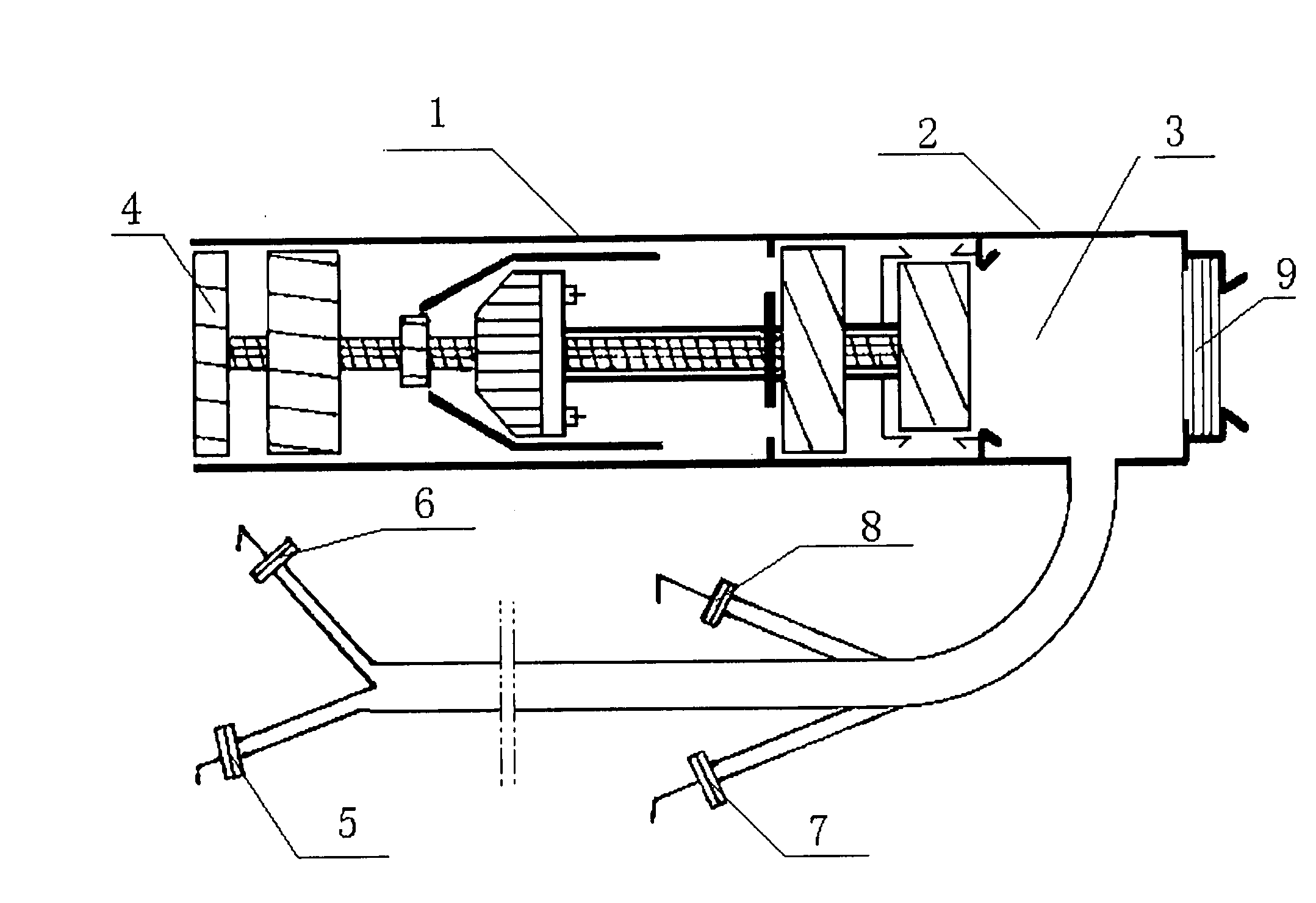
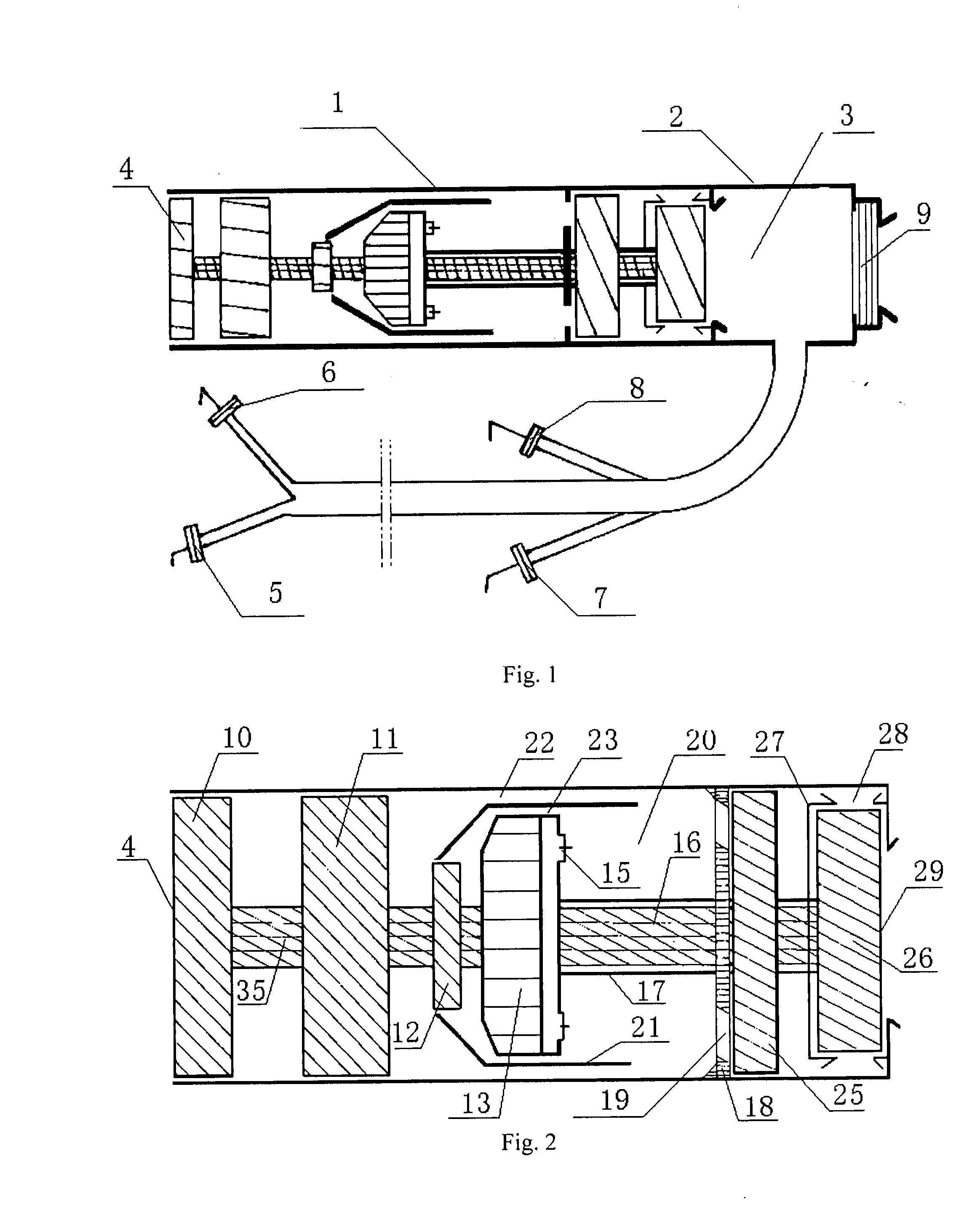
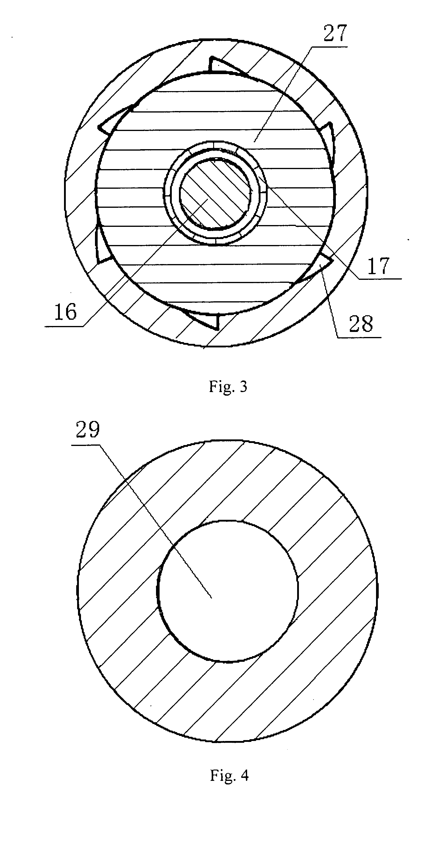
[0041]In the detailed description, each component will be represented by one reference numeral respectively, wherein: 1 refers to a turbo-charged air compressor; 2 refers to a housing of titanium alloy; 3 refers to a pressure chamber; 4 refers to an air intake port; 5 refers to a front right nozzle member; 6 refers to a front left nozzle member; 7 refers to a rear right nozzle member; 8 refers to a rear left nozzle member; 9 refers to a rear nozzle member; 10 refers to an intake compressor; 11 refers to a large supercharging compressor module; 12 refers to a small supercharging compressor; 13 refers to a speed changed gear box; 14 refers to an air-flow switching valve member; 15 refers to a fuel nozzle; 16 refers to a rear transmission shaft; 17 refers to a heat insulation cover for resisting high temperature; 18 refers to an air ejection fence; 19 refers to a...


PUM


Abstract

The present invention relates to an air compression type engine for aviation. The conventional aircraft engine is complicated in structure, consumes expensive aero fuel, and produces extremely loud noise during operation. Therefore, the present invention employs a turbo-charged air compressor to generate high temperature and high pressure gas in the pressure chamber, and uses the reaction thrust force generated by ejecting the compressed air through the nozzle to make the aircraft vertically take off/land, suspend in the air and fly forwardly. Benefited from the simple structure, the manufacture cost of the aircraft engine can be dramatically decreased. Vertically raising and landing the aircraft can be achieved by changing the ejection directed of the compressed air in the pressure chamber. The commonly used gasoline or diesel, which is cost saving and capable of combusting with a high combustion value, can be used instead of the expensive aviation kerosene. Further, the generated noise is quite small. By means of above arrangement, it is possible to manufacture a jet type manned craft like a car, which can be operated by common people to vertically take off/land and shuttle conveniently in the downtown area through simple operation procedure.

Description

FIELD OF INVENTION[0001]The present invention relates to a jet-type turbine engine, and particularly to an air compression type engine for aviation.BACKGROUND OF INVENTION[0002]Nowadays, a known jet-type aviation engine is configured to draw the air by intake compressor, warm the intake air by the heat generated through burning the aviation kerosene within the combustion chamber, eject rapidly the intake air backward after expanded due to the warming, and then utilize the reaction force thus achieving the forward flight of an aircraft. In such engine, there exist several disadvantages listed as below:[0003](1). The configuration of the engine is very complicated, and the manufacture cost of the engine is unbearably high. Unlike an internal combustion engine used in a common vehicle, the structure of which is very simple and manufacture cost of which is low, the jet-type aviation engine usually costs up to millions of dollars, which negatively limits the manufacture and application o...

Claims


Application Information

Patent Timeline
IPC IPC(8): F02K1/00F02K1/54F02K1/56F02K3/04
CPCF02C3/04F02C3/107F05D2220/90Y02T50/671F02K1/002Y02T50/60
Inventor CHANG, STANLEY
Owner CHANG STANLEY
Why Eureka
Try Eureka