Regeneration of an Aqueous Solution from an Acid Gas Absorportion Process by Matrix Stripping

a technology of acid gas absorption and matrix stripping, which is applied in the direction of separation processes, liquid degasification, hydrogen sulfides, etc., can solve the problems of high capital cost of columns, pumps and exchangers, initial solvent and operating cost, and impair the effect of technology

Inactive Publication Date: 2008-06-05
BOARD OF RGT THE UNIV OF TEXAS SYST
View PDF13 Cites 40 Cited by
  • Summary
  • Abstract
  • Description
  • Claims
  • Application Information

AI Technical Summary

Problems solved by technology

A major challenge facing the implementation of aqueous absorption / stripping on a large scale for CO2 capture is the high capital cost of columns, pumps and exchangers and initial solvent and operating cost (reboiler duty, pump circulation rate, solvent make-up) of the technology.
Any problems or shortcomings enumerated in the foregoing are not intended to be exhaustive but rather are among many that tend to impair the effectiveness of previously known techniques.
Other noteworthy problems may also exist; however, those presented above should be sufficient to demonstrate that apparatus and methods appearing in the art have not been altogether satisfactory and that a need exists for the techniques disclosed herein.

Method used


Image

  • Regeneration of an Aqueous Solution from an Acid Gas Absorportion Process by Matrix Stripping
  • Regeneration of an Aqueous Solution from an Acid Gas Absorportion Process by Matrix Stripping
  • Regeneration of an Aqueous Solution from an Acid Gas Absorportion Process by Matrix Stripping

Examples


example 1

Modeling of Four Alternative Stripper Configurations with Five Different Solvents

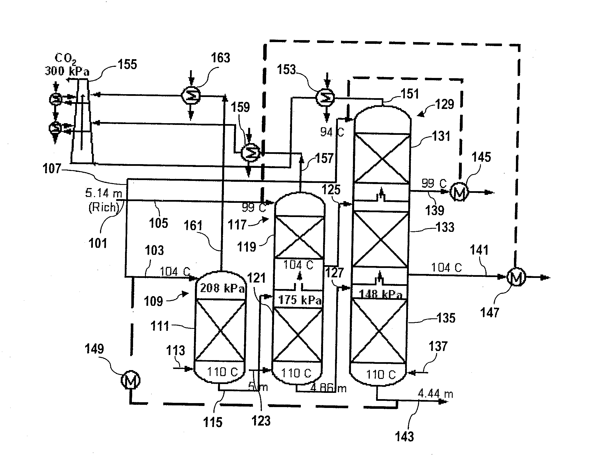
[0052]For this Example, four new stripper configurations (matrix, internal exchange, flashing feed, and multipressure with split feed) were evaluated with five different solvents: 7 m (30 wt %) monoethanolamine (MEA), potassium carbonate promoted by piperazine (PZ), promoted MEA, methyldiethanolamine (MDEA) promoted by PZ and hindered amines. The configurations, solvents, and operating parameters were evaluated to determine which configurations, solvents, and operating parameters result in the greatest energy savings over the baseline configuration and the improved baseline configuration.

A. ANALYSIS OF THE BASELINE CONFIGURATION

[0053]Previous investigation suggests the optimum generic solvent at 160 kPa (normal pressure) is one with a higher heat of desorption than 7 m (30-wt %) MEA (Oyenekan et al., 2006). Since PZ / K2CO3 solvents have heats of desorption lower than 7 m MEA, they cannot be employed in a...

example 2

Modeling of Matrix Stripping Configuration with Two Different Solvents

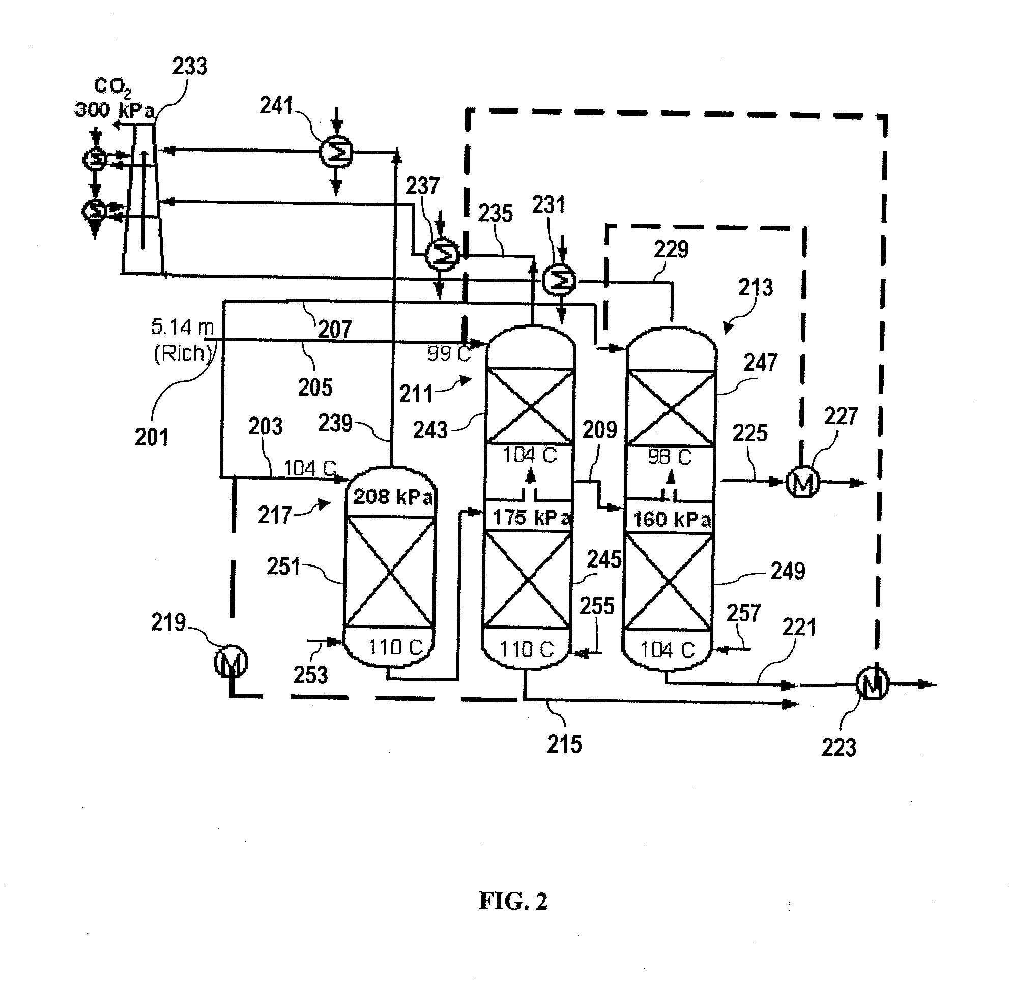
[0120]An equilibrium stripper model for aqueous solvents developed in Aspen Custom Modeler (ACM) was used to evaluate a matrix stripping configuration with two different solvents and three different operating scenarios for comparison to a baseline scenario.

[0121]All of these cases were calculated with a 5° C. approach in the cross-exchanger. The low pressure stripper or only stripper in each case was designed to operate at 160 kPa. “Percent split” for each case is defined as the portion (by mass) of the rich solvent stream that is fed to the second stripper divided by of the portion (by mass) of the rich solvent stream that is fed to the first stripper, multiplied by 100%. The rich solvent feed rate to the high pressure column of the double matrix configuration was defined as the split ratio times the feed to the high pressure column. The pressure ratio of the first column to the second column was also optimized.

[...


PUM


Abstract

Carbon dioxide and other acid gases are removed from gaseous streams using aqueous absorption and stripping processes. By replacing the conventional stripper used to regenerate the aqueous solvent and capture the acid gas with a matrix stripping configuration, less energy is consumed. The matrix stripping configuration uses two or more reboiled strippers at different pressures. The rich feed from the absorption equipment is split among the strippers, and partially regenerated solvent from the highest pressure stripper flows to the middle of sequentially lower pressure strippers in a “matrix” pattern. By selecting certain parameters of the matrix stripping configuration such that the total energy required by the strippers to achieve a desired percentage of acid gas removal from the gaseous stream is minimized, further energy savings can be realized.

Description

[0001]This application claims the benefit of priority to U.S. Provisional Patent Application No. 60 / 849,355, filed Oct. 4, 2006, which is hereby incorporated by reference in its entirety.[0002]The government may own certain rights in relation to the present invention pursuant to grant number DE-FC26-02NT41440 from the U.S. Department of Energy.BACKGROUND[0003]I. Field[0004]The present invention relates generally to the removal and capture of acid gases, including carbon dioxide, from flue gas or other gases through aqueous absorption and stripping processes. More particularly, it provides methods for reducing the energy consumption of such absorption and stripping processes.[0005]II. Description of Related Art[0006]A common viewpoint held by a significant segment of the environmental community is that carbon dioxide released into the air plays a major role in global climate change. Thus, global climate change initiatives such as the Kyoto Protocol have identified the curtailment of ...

Claims


Application Information

Patent Timeline
Patent Type & Authority Applications(United States)
IPC IPC(8): B01D19/00
CPCB01D3/143B01D53/1425B01D3/4211B01D3/38Y02P70/10
Inventor ROCHELLE, GARY T.OYENEKAN, BABATUNDE A.
Owner BOARD OF RGT THE UNIV OF TEXAS SYST
Why Eureka
Try Eureka