
Concave laser-resurfaced part, method and device for producing it

a laser-resurfacing and concave technology, applied in the direction of manufacturing tools, solventing devices, other domestic objects, etc., can solve the problems of inability to suitably propagate along the penetration direction right to the resurfacing zone, divergent laser beam, etc., and achieve the effect of free of any risk of degrading or lowering the effectiveness

Inactive Publication Date: 2008-06-05
TECHNOSYM SRL
View PDF18 Cites 17 Cited by
  • Summary
  • Abstract
  • Description
  • Claims
  • Application Information

AI Technical Summary

Benefits of technology

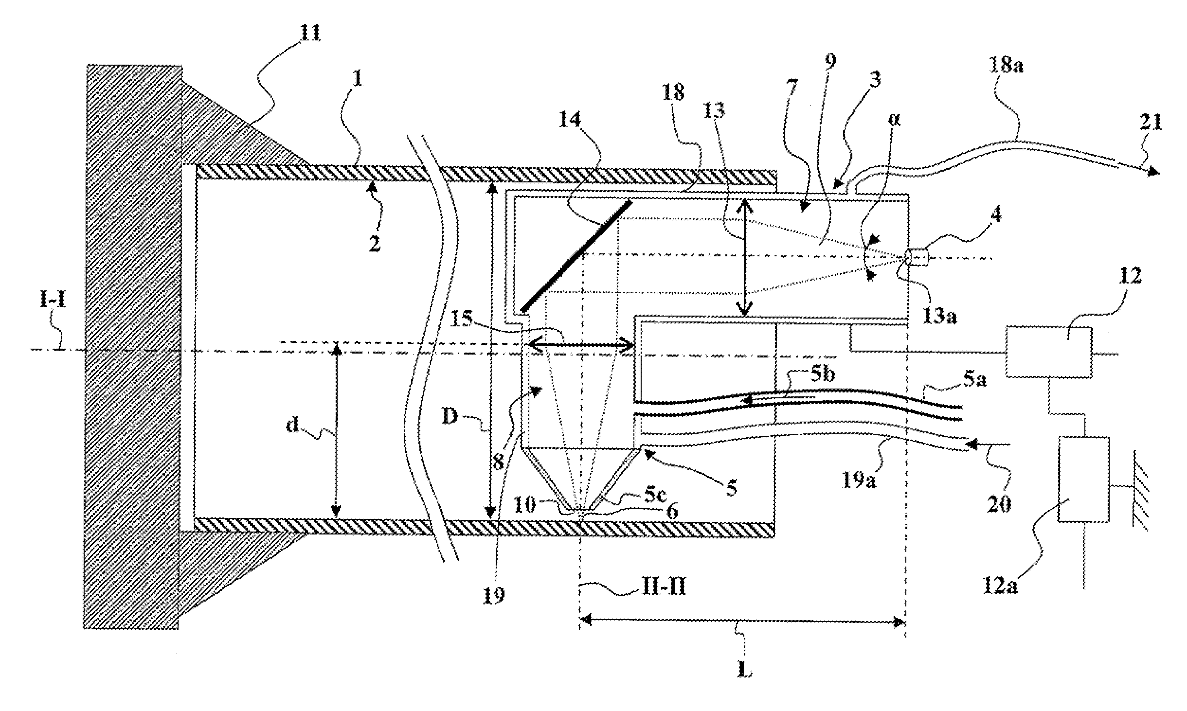
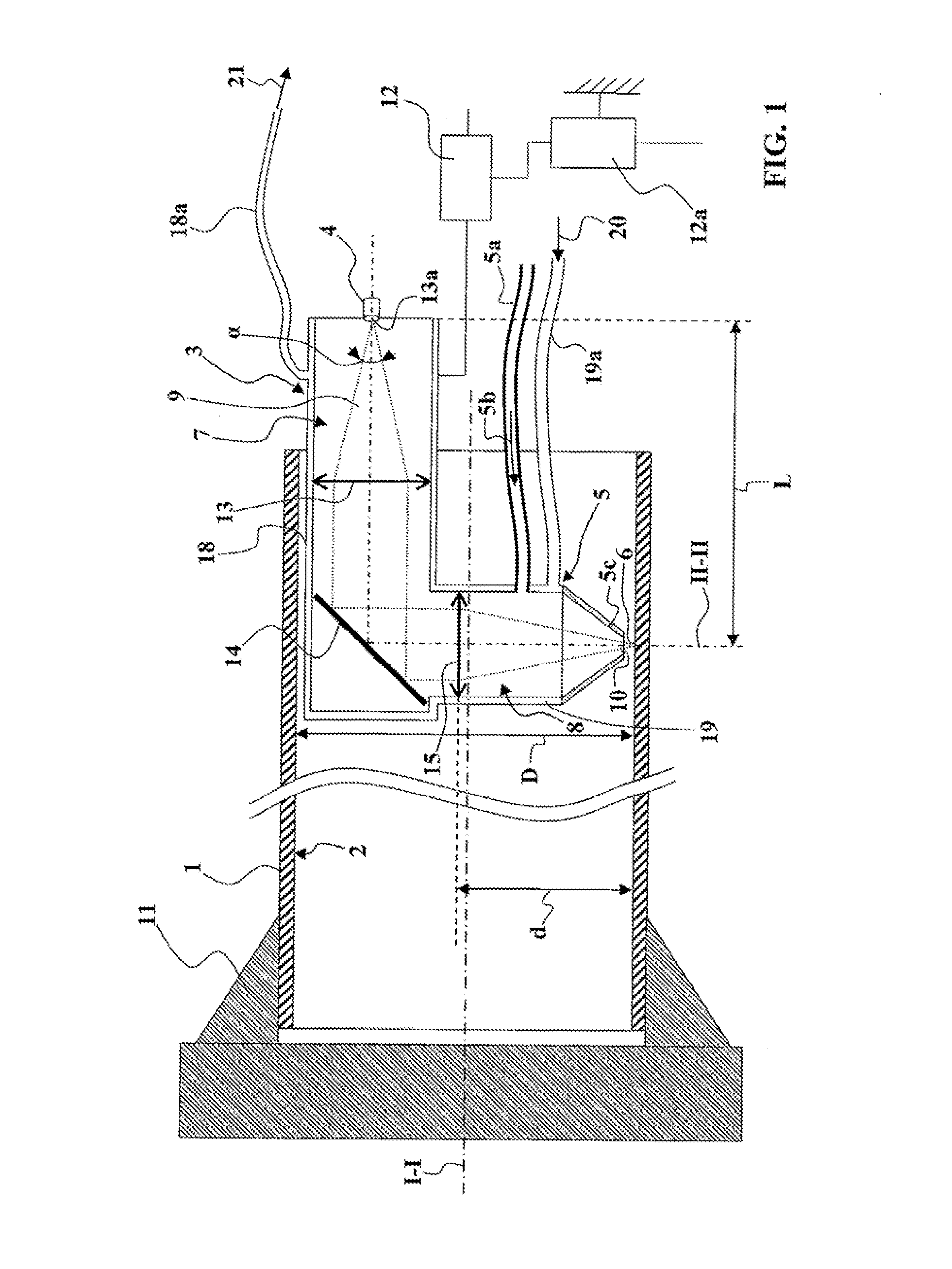
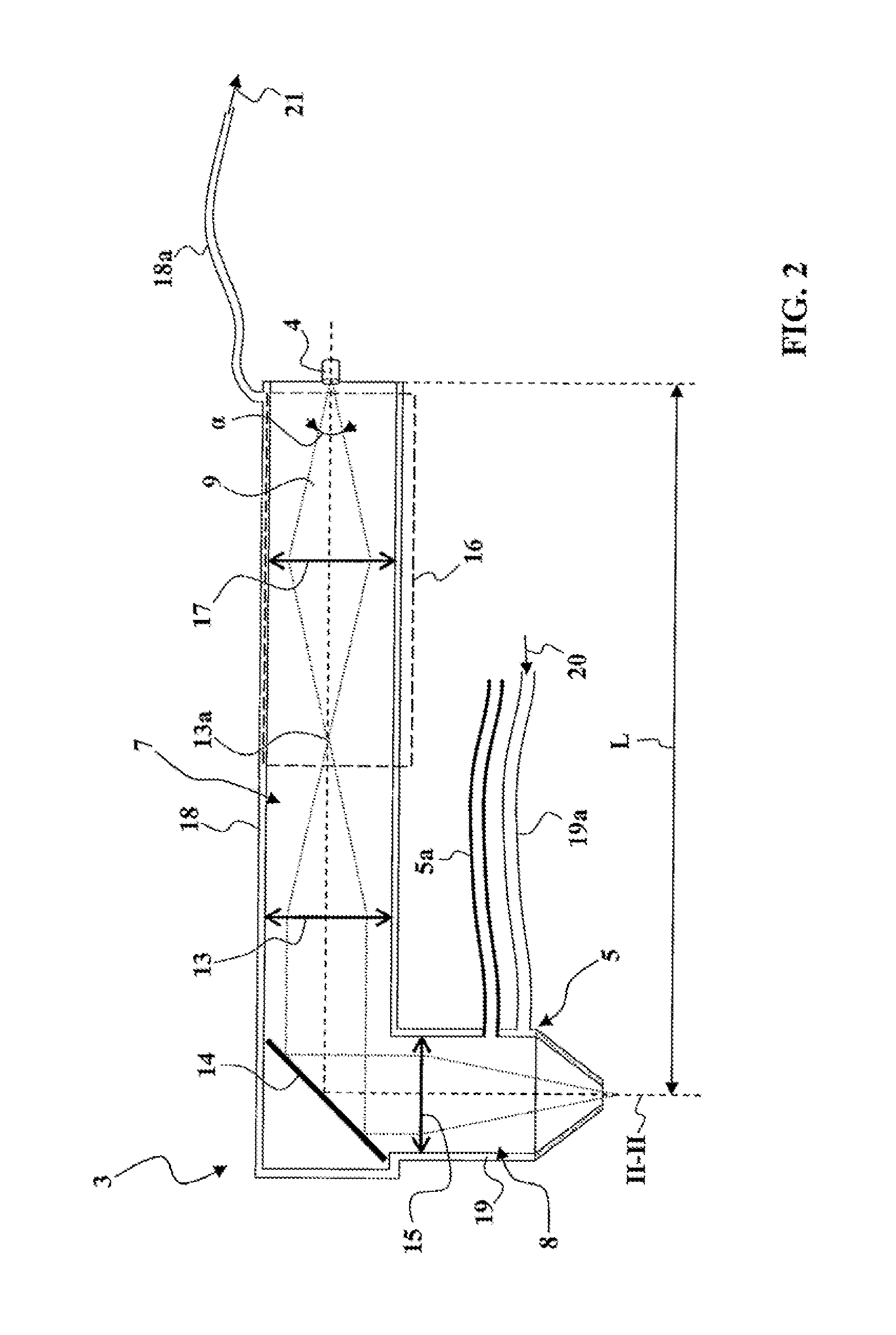
The present invention is aimed at providing a device for resurfacing the concave face of a tubular part using a laser beam. The device is designed to be cost-effective and easy to use, while still effectively resurfacing the part. The invention solves the problem of heating the inside of the tubular part by using a diode laser source, which can derade or lower the effectiveness of the resurfacing material. The device includes a laser beam source, resurfacing material delivery means, and optical components to direct the laser beam to the resurfacing zone. The laser beam is initially concentrated and then deflected to a radial direction, where it is directed by a second convergent lens to the object focal point of a first convergent lens. The first convergent lens receives the laser beam and sends it along the penetration direction as a parallel-ray beam. The laser beam is then focused onto the object using an optical insert, which allows for effective confinement of the laser beam. The use of a diode laser source and a simple optical arrangement makes the device insensitive to heating and allows for effective confinement of the laser beam.

Problems solved by technology

The diode laser source is effective and inexpensive but it does have the drawback of producing a divergent laser beam, which is of course incapable of suitably propagating along the penetration direction right to the resurfacing zone.

Method used


Image

  • Concave laser-resurfaced part, method and device for producing it
  • Concave laser-resurfaced part, method and device for producing it
  • Concave laser-resurfaced part, method and device for producing it

Examples


Embodiment Construction

[0081]FIG. 1 shows a tubular part 1 having a concave face 2 to be resurfaced. The tubular part 1 extends along a longitudinal axis I-I.

[0082]The resurfacing device includes a laser source, which is a diode laser 4. Although the diode laser 4 is shown here as being very compact, it should be understood that the means for supplying and controlling the diode laser 4 are not shown and that these may take up a very considerable amount of space, and larger than the inside diameter D of the tubular part 1, so that it is not possible for the diode laser 4 and its supply and control means to penetrate inside the tubular part 1.

[0083]The resurfacing device includes resurfacing material delivery means 5, the resurfacing material being based on hard refractory particles and metal alloy particles. The resurfacing material delivery means 5 deliver the resurfacing material close to a resurfacing zone 6 on the concave face 2 of the tubular part 1 to be resurfaced.

[0084]The resurfacing device includ...


PUM

PropertyMeasurementUnit
diameteraaaaaaaaaa
lengthaaaaaaaaaa
diameteraaaaaaaaaa

Abstract

Device for resurfacing a concave face (2) of a tubular part (1) by supplying resurfacing material and energy by a laser, comprising a laser source for generating a laser beam (9), resurfacing material delivery means (5) based on hard refractory particles and metal alloy particles, in order to deliver the resurfacing material close to a resurfacing zone (6) on the concave face (2) of the tubular part (1) to be resurfaced, laser beam delivery means (7) and directing means (8) for directing the laser beam (9) into the resurfacing zone (6). The laser source is a diode laser (4) and the laser beam delivery means (7) conduct the latter over a penetration length (L) along a penetration direction and then the directing means (8) deflect the laser beam (9) into a radial direction (II-II) away from the penetration direction, so that the laser source may lie outside the tubular part (1) and the laser beam delivery means (7) may be axially engaged completely or partly in the tubular part (1).

Description

TECHNICAL FIELD OF THE INVENTION[0001]The present invention relates to a device for resurfacing a part by supplying resurfacing material containing hard refractory particles and metal alloy particles.[0002]More particularly, the invention relates to a device for resurfacing a concave face of a tubular part by supplying resurfacing material in powder form and by supplying energy by a laser.[0003]Tubular parts having a hard refractory or metal alloy layer on their concave face are commonly used so as to be cut up into sections of variable length in order to produce bearings for the guiding of rotating shafts. Such tubular parts may also constitute cylinders for guiding the pistons in an internal combustion engine.[0004]Various methods are already known for resurfacing the concave face of a tubular part.[0005]Among these, the resurfacing of a concave face of a tubular part by supplying resurfacing material and energy by a laser proves to be particularly effective. This is because using...

Claims


Application Information

Patent Timeline
Patent Type & Authority Applications(United States)
IPC IPC(8): B23K26/20B05C9/02H01S3/08
CPCB23K26/0639B23K26/0648B23K26/0665B23K26/0823B23K26/106B23K35/0244B23K26/1476B23K26/34B23K2201/06C23C24/10B23K26/1411B23K26/064B23K26/144B23K2101/06
Inventor DEZERT, DIDIERCREPIN, JEAN-BAPTISTE
Owner TECHNOSYM SRL
Learn More