Charging system, charging apparatus and battery pack

a charging system and battery pack technology, applied in the direction of electric vehicles, transportation and packaging, electric generators, etc., can solve the problems of enlarge the short circuit, slow charging speed, and long time to increase the charge capacity, so as to increase the battery capacity of a secondary battery, and prevent the secondary battery from deteriorating

Inactive Publication Date: 2008-06-05
PANASONIC CORP
View PDF2 Cites 31 Cited by
  • Summary
  • Abstract
  • Description
  • Claims
  • Application Information

AI Technical Summary

Benefits of technology

[0019]It is an object of the present invention to provide a charging system, a charging apparatus and a battery pack which are capable of increasing the batte

Problems solved by technology

In the constant-voltage charge, however, the closer the secondary battery comes to the full charge, the less the charging current becomes, thus making the charge slower.
Hence, if the current value I2 is set to zero amperes, it takes a long time to increase a little charge capacity.
As a result, a short-circuit current passing through the lithium dendrite may melt the separator, enlarge the short circuit's part and destroy the battery.
This short-circuit current can melt the separator, enlarge the short circuit's part and destroy the battery.
Hence, a disadvantage arises in that the charging vol

Method used


Image

  • Charging system, charging apparatus and battery pack
  • Charging system, charging apparatus and battery pack
  • Charging system, charging apparatus and battery pack

Examples


Embodiment Construction

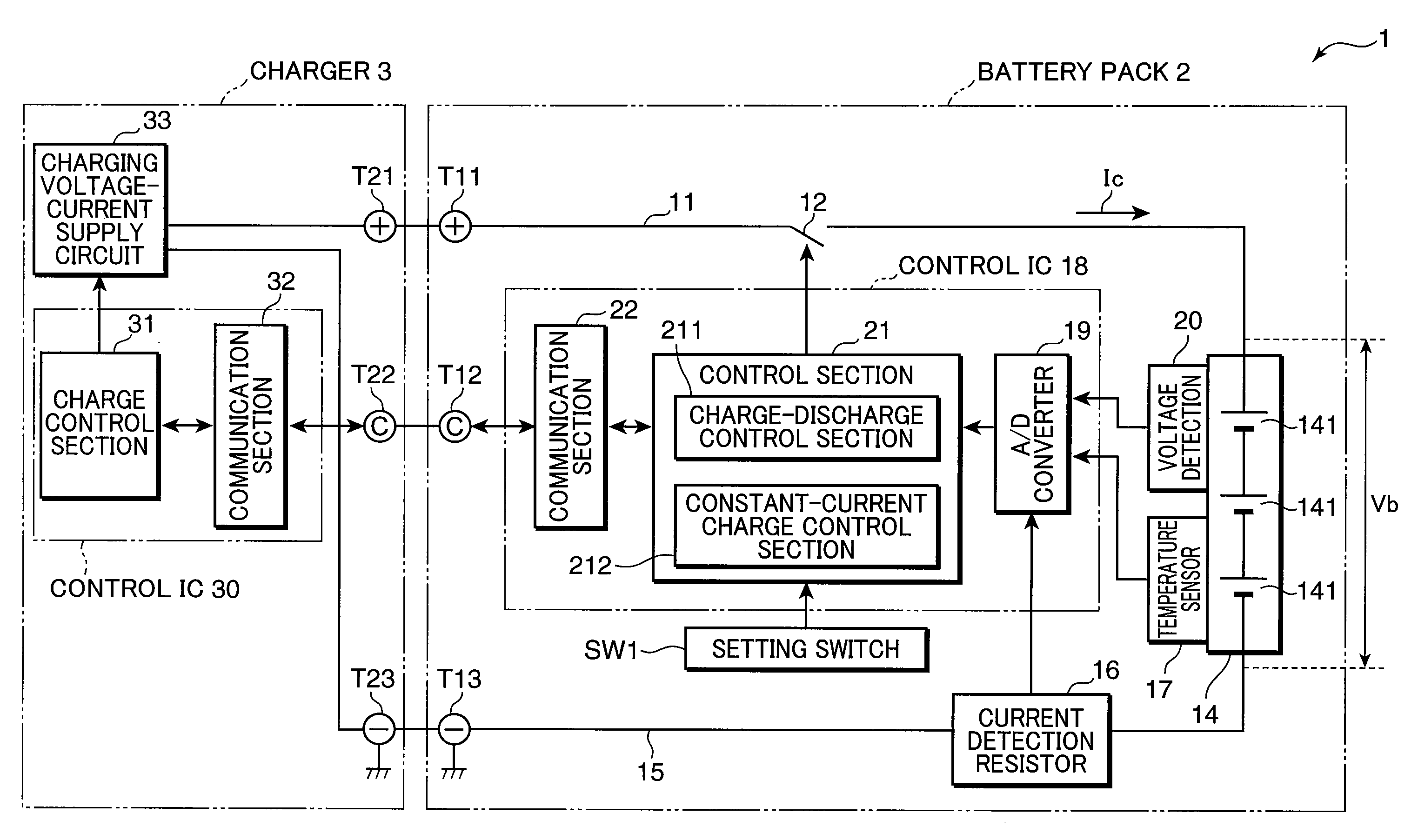
[0034]Hereinafter, a charging system according to an embodiment of the present invention will be described with reference to the attached drawings. In each figure, component elements are given the same reference characters and numerals, as long as they are identical to one another. Thus, their description is omitted. FIG. 1 is a block diagram, showing an example of the configuration of the charging system according to an embodiment of the present invention. This charging system 1 is configured by a battery pack 2, and a charger 3 which charges it. Further including load equipment (not shown) supplied with electric power from the battery pack 2, an electronic-equipment system may also be configured. In addition, the charger 3 may also be formed as a part of such load equipment. In that case, the battery pack 2 is charged by the charger 3 in FIG. 1, but the battery pack 2 may also be attached to the load equipment and charged through the load equipment. The battery pack 2 and the char...


PUM


Abstract

A charging system is provided which includes: a secondary battery which includes a heat-resistant member having a heat-resistance property between a negative electrode and a positive electrode thereof; a charging-voltage supply section which supplies a charging voltage for charging the secondary battery; a charge control section which controls the operation of the charging-voltage supply section on the basis of a reference voltage corresponding to the voltage between the negative electrode and the positive electrode in a full-charge state where the lithium-reference electric potential of the negative electrode is substantially zero volts; and a mode-setting acceptance section which chooses and accepts the setting of either of an ordinary charge mode and a high-voltage charge mode, in which if the mode-setting acceptance section accepts the setting of the ordinary charge mode, then the charge control section allows the charging-voltage supply section to supply, to the secondary battery, a first set voltage equal to, or below, the reference voltage as the charging voltage, and if the mode-setting acceptance section accepts the setting of the high-voltage charge mode, then the charge control section allows the charging-voltage supply section to supply, to the secondary battery, a second set voltage above the reference voltage as the charging voltage, so that the secondary battery is charged.

Description

BACKGROUND OF THE INVENTION[0001]1. Field of the Invention[0002]The present invention relates to a charging system and a charging apparatus which charge a secondary battery, and a battery pack provided with a secondary battery.[0003]2. Description of the Background Art[0004]FIG. 8 is a graphical representation, showing a method of managing a charging voltage and a charging current according to a prior art. FIG. 8 shows graphs, indicating that a constant-current and constant-voltage (CCCV) charge is given to a lithium-ion battery. Fluctuations are shown in a terminal voltage α1 of a secondary battery, a charging current α2 supplied to the secondary battery and an SOC (or state of charge) α3.[0005]First, in the case of such a CCCV charge (e.g., refer to Japanese Patent Laid-Open No. H6-78471 specification), the charge starts from a constant-current (CC) charge range. Within the constant-current (CC) charge range, a predetermined constant current I1 is supplied as the charging current,...

Claims


Application Information

Patent Timeline
IPC IPC(8): H02J7/00
CPCH01M10/052H01M10/4235Y02T10/7011H02J7/0073H01M10/441H02J7/0071Y02E60/10
Inventor NISHINO, HAJIME
Owner PANASONIC CORP
Why Eureka
Try Eureka