Fuel supporting attachment and fuel inlet mechanism

a technology of fuel inlet mechanism and supporting attachment, which is applied in the direction of nuclear reactors, nuclear elements, greenhouse gas reduction, etc., can solve the problems of damage to the fuel rod and the fuel spacer, and increase the pressure loss of the fuel assembly. , to achieve the effect of minimizing pressure loss and simple structur

Inactive Publication Date: 2008-06-05
KK TOSHIBA
View PDF13 Cites 19 Cited by
  • Summary
  • Abstract
  • Description
  • Claims
  • Application Information

AI Technical Summary

Benefits of technology

[0011]In view of the foregoing, it is an object of the invention to provide a fuel supporting attachment, fuel inlet mechanism and a fuel assembly for preventing or controlling a foreign substance from passing through and minimizing pressure loss, with a simple structure with no need of modifying or changing the fuel assembly or its design with regard to a new fuel assembly and / or a used fuel assembly.

Problems solved by technology

In accordance with a long period of use, there is a tendency of increasing damage phenomena of the fuel member, and thus it has been pointed out that when such a fuel damage is caused, the operation efficiency has worsen due to stopping operation of the plant, replacement of the damaged fuel or the like.
As one of problems related to operation of the nuclear reactor, it is pointed out that foreign substances having various dimensions are piled up in the fuel assembly.
In operation of the nuclear reactor, the foreign substance present inside of the nuclear reactor and the primary system is moved by the coolant, and there is a possibility that the foreign substance is mixed into the fuel assembly and damages the fuel rod and the fuel spacer which are constituent elements of the fuel assembly.
When the wire-like foreign substance which flows into the fuel assembly, is caught by the fuel spacer and vibrated by being exerted by Karman's vortex generated by the coolant flow and brought into contact with a surface of the fuel rod, the foreign substance wears and damages the cladding tube of the fuel rod.
This wear is referred to as fretting wear and damages the fuel rod in a combination with acceleration of corrosion under high temperature and high pressure conditions in the nuclear reactor.
In order to prevent such an adverse influence of the foreign substance on the fuel assembly, in recent times, there has been promoted a trial of integrating a filter mechanism at a lower tie plate of a new fuel assembly, however, integration of the foreign substance filter to the fuel assembly brings about an increase in pressure loss in view of designing the fuel assembly and therefore, the foreign substance filter cannot be integrated to a certain kind of 9×9 type fuel.
Further, when the filter function is integrated to a new fuel assembly, it takes about five years through seven years until all of the conventional fuel assemblies charged into the nuclear reactor have been replaced by the fuel assemblies having the filter function.
However, in providing the filter function to the fuel assemblies being used, it is necessary to carry out disintegration and reintegration of the fuel assemblies inside of the atomic power generation plant by remote operation, which is very expensive.
Moreover, according to the above-described conventional foreign substance filter, the diameter of holes of the filter must be reduced to hamper a foreign substance from passing by a wire gauze or a porous plate, therefore pressure loss increases and a flow rate of the passing fluid is reduced and also there is a possibility that it is difficult to ensure a necessary flow rate.
As a result, a linear or a strip-like foreign substance cannot necessarily be prevented from passing.
Further, the above-mentioned conventional foreign substance filter is frequently constructed by a constitution satisfying its function by overlapping several sheets of metal gauzes or porous plates and, thus, if an integration accuracy of the metal gauzes or the porous plates is poor, there is a possibility of significantly deteriorating the function.
However, according to any of these, it is necessary to work on the lower tie plate, and further, the structure is complicated.
Further, in recent years, there has been proposed a plan of preventing a foreign substance from being mixed with a fuel assembly by inserting a foreign substance filter from an upper side of a fuel supporting attachment to an inner portion thereof, however, the foreign substance filter may interfere with a seat face of the lower tie plate of the fuel assembly in taking out or charging the fuel assembly and stable function cannot be achieved.

Method used


Image

  • Fuel supporting attachment and fuel inlet mechanism
  • Fuel supporting attachment and fuel inlet mechanism
  • Fuel supporting attachment and fuel inlet mechanism

Examples


first embodiment

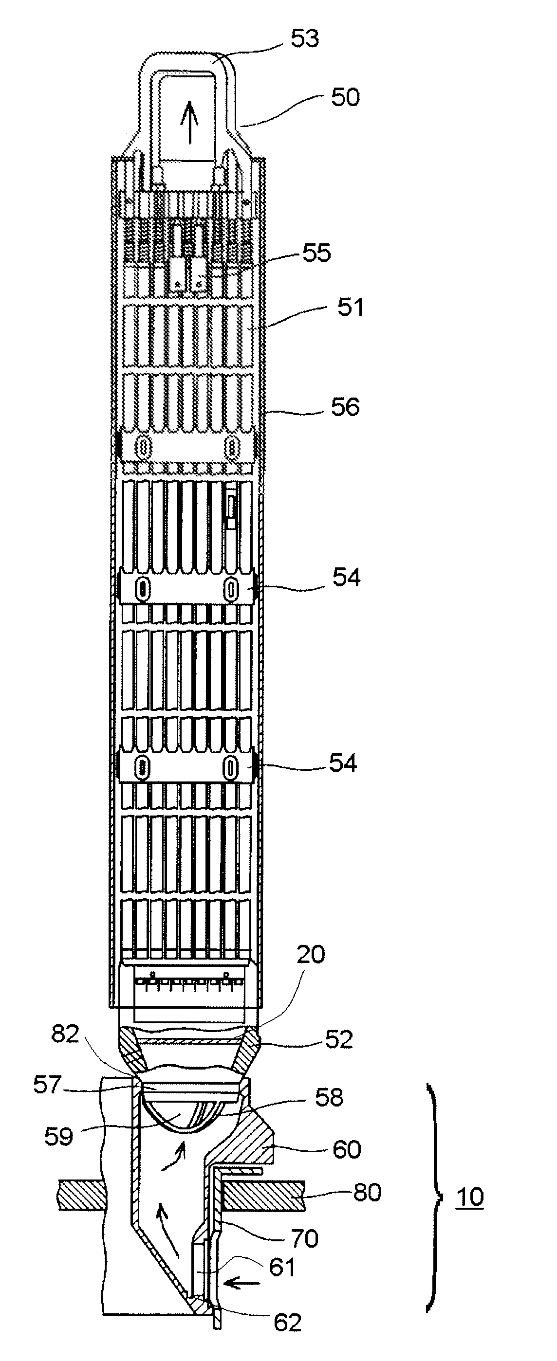
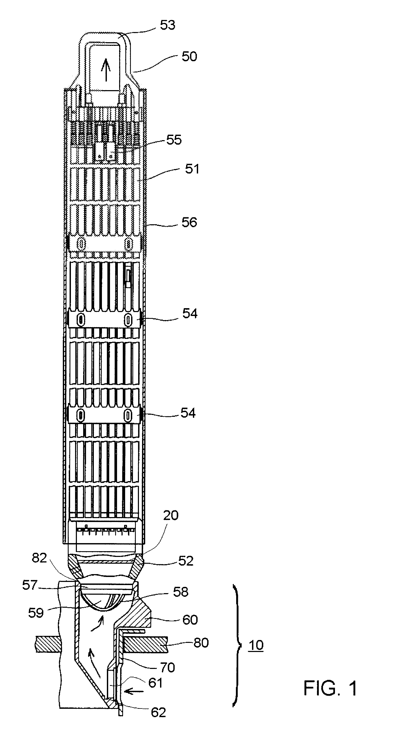
[0054]FIG. 1 shows a fuel assembly according to a first embodiment of this invention, in which it shows an example of this embodiment being applied to a fuel assembly for a boiling water reactor. The fuel assembly 50 includes a plurality of portions of fuel rods 51 aligned in a lattice shape and a single portion or a plurality of portions of water rods 55. Lower ends and upper ends of the fuel rods 51 and water rods 55 are fixed to a lower tie plate 52 and an upper tie plate 53, respectively. There are a plurality of fuel spacers 54 between the lower tie plate 52 and the upper tie plate 53 (here only three fuel spacers are shown representatively), thereby intervals among the fuel rods 51 and the water rods 55 are maintained. Sides of the fuel assembly 50 are covered by a channel box 56, having a section approximately in a square shape, an upper end and a lower end of which are opened. An inlet nozzle 57 constituting an inlet of coolant into the fuel assembly 50 is arranged at a lowe...

second embodiment

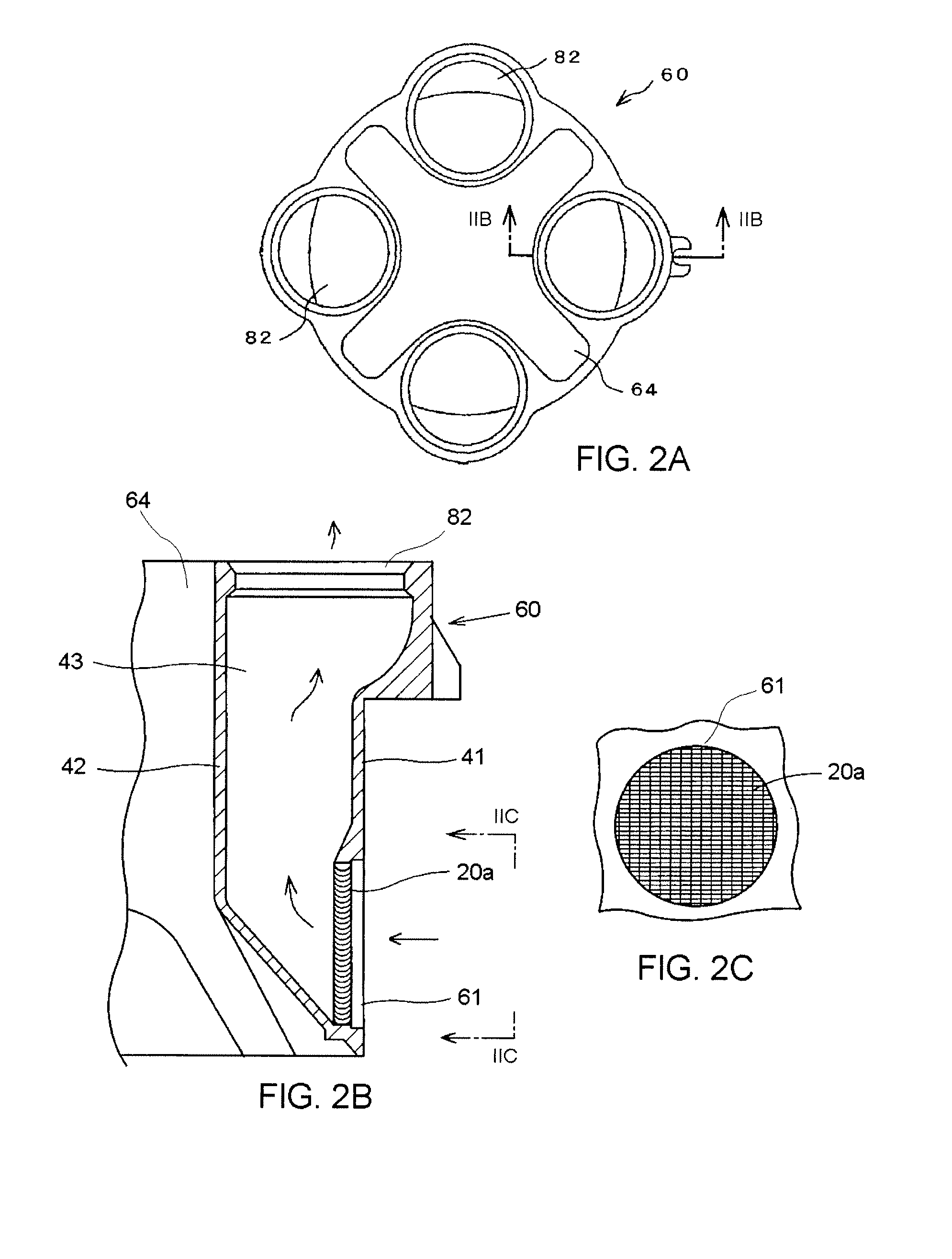
[0056]Next, an explanation of a fuel inlet mechanism according to a second embodiment of this invention will be given in reference to FIGS. 2A, 2B and 2C. A fuel inlet mechanism 10 of this embodiment is comprised of mostly a fuel introducing attachment 60, however, the fuel inlet mechanism could be any structure introducing upstream of the fuel assembly that provides coolant into the fuel assembly.

[0057]The fuel supporting attachment 60 is mounted on the core support plate 80 as shown in FIGS. 2A, 2B and 2C, and each fuel supporting attachment 60 supports four fuel assemblies 50 from the lower side and has four openings 82 to pass the coolant into the fuel assemblies 50. In the fuel supporting attachment 60, an outer wall 41 and an inner wall 42 constitute a coolant passage 43 under the opening 82. A coolant introducing hole 61 is arranged under the outer wall 41, that is, at each gate portion of the fuel supporting attachment 60 directed toward the respective opening 82, and each c...

third embodiment

[0059]Next, an explanation of detailed structure of the above-mentioned filters 20 or 20a will be given according to a third embodiment of this invention. Structures of the filter 20 and the filter 20a are common to both filters and the following explanation will be given of the filter 20 representatively.

[0060]The filter 20 is constituted by aligning a number of passages 3 in a shape of a character V (or “Λ” lambda in the Greek alphabet, that is, a passage has a bent portion) shown in FIG. 3 in parallel. A shape of the flow path 3 viewed from a flow direction D is, for example, a rectangular shape as shown in FIG. 4A or a circular shape as shown in FIG. 4B. In the case of the rectangular hole 1 shown in FIG. 4A, a condition of catching a linear foreign substance 4 with a length L (for example, L is assumed to be about ten millimeters) in a direction orthogonal to the flow by the filter 20 is L>√(A2+B2), wherein a transverse length and a vertical length of the hole are designated by...


PUM


Abstract

A fuel inlet mechanism to introduce a coolant into a fuel assembly configured to be charged in a light water nuclear reactor, includes, a filter catching a foreign substance included in the coolant on an upstream side of the fuel assembly, the filter having a plurality of through holes to pass the coolant, and the through holes having an inlet portion, an outlet portion and at least one bent portion to a degree by which the outlet portion cannot be seen through from the inlet portion by a straight line.

Description

[0001]This present application is a divisional of U.S. patent application Ser. No. 11 / 207,777, filed Aug. 22, 2005, which is a continuation of U.S. patent application Ser. No. 10 / 195,126, filed Jul. 15, 2002, the entire contents of both applications are incorporated hereby by reference.CROSS-REFERENCE TO RELATED APPLICATIONS[0002]This application is based upon and claims the benefit of priority from Japanese Patent Applications No. 2001-215379 filed on Jul. 16, 2001, No. 2001-318049 filed on Oct. 16, 2001, and No. 2002-147853 filed on May 22, 2002, the entire contents of which are incorporated herein by reference.BACKGROUND OF THE INVENTION[0003]1. Field of the Invention[0004]This invention relates to a fuel assembly used in a light-water nuclear reactor, a fuel supporting attachment for supporting a fuel assembly, and a fuel inlet mechanism for introducing coolant into a fuel assembly.[0005]2. Description of the Related Art[0006]Generally, as a filter for catching a foreign substan...

Claims


Application Information

Patent Timeline
Patent Type & Authority Applications(United States)
IPC IPC(8): G21C15/243G21C3/32G21C5/06
CPCG21C3/3206G21C5/06G21Y2002/201Y02E30/40G21Y2002/304G21Y2004/30G21Y2002/301Y02E30/30
Inventor UKAI, MASARUTSUMITA, KOSAKUKATO, RYOMAFUKAMICHI, KENJIROYAMADA, YUJISATO, MAKOTOSHIMAZU, TADAAKITANABE, TOMOHARUMATSUMURA, HIROTOSHIMATSUNAGA, KEIJIOKUDA, KEN
Owner KK TOSHIBA
Why Eureka
Try Eureka