Fan for a gas burner system

a technology of gas burner and fan, which is applied in the direction of waterborne vessels, blast-producing apparatus, machines/engines, etc., can solve the problems of anti-static material, and achieve the effect of saving space and additional depth

Active Publication Date: 2008-06-05
MINEBEAMITSUMI INC
View PDF7 Cites 28 Cited by
  • Summary
  • Abstract
  • Description
  • Claims
  • Application Information

AI Technical Summary

Benefits of technology

[0012]The fan according to the invention is extremely compact and can achieve a space saving of approximately 20% solely by the shape of its fan housing alone compared to known fans for gas burners, as described in more detail below. The design and arrangement of the aperture of the fan housing makes it possible to dispose the downstream device for admitting the combustion gas such that it almost abuts the fan housing in any orientation so desired. By disposing the electric motor to drive the impeller at the center of the impeller, additional space saving in depth of approximately 50% can be achieved. Furthermore, problems involved in the sealing of the shaft and concerning the elastic support of the drive on the fan housing can be avoided or easily solved.
[0013]In the preferred embodiment of the invention, the fan housing and the impeller are made of plastics. Most preferably, the fan housing and the impeller are made up of one or more injection molded plastic parts, the use of anti-static material being unnecessary. Since the combustion gas is only fed in at the outflow side of the fan, there is no danger of a combustible gas / air mixture being formed in the interior of the fan housing. This not only makes it possible to dispose the drive motor in the interior of the fan housing, but also to make the housing and impeller out of plastics. This means that the fan housing and the impeller neither need to be made of a conductive metal material that is complicated to machine nor need to be made of an anti-static material that is comparatively expensive. In addition, the fan housing need not be sealed gas-proof.

Problems solved by technology

This means that the fan housing and the impeller neither need to be made of a conductive metal material that is complicated to machine nor need to be made of an anti-static material that is comparatively expensive.

Method used


Image

  • Fan for a gas burner system
  • Fan for a gas burner system
  • Fan for a gas burner system

Examples


Embodiment Construction

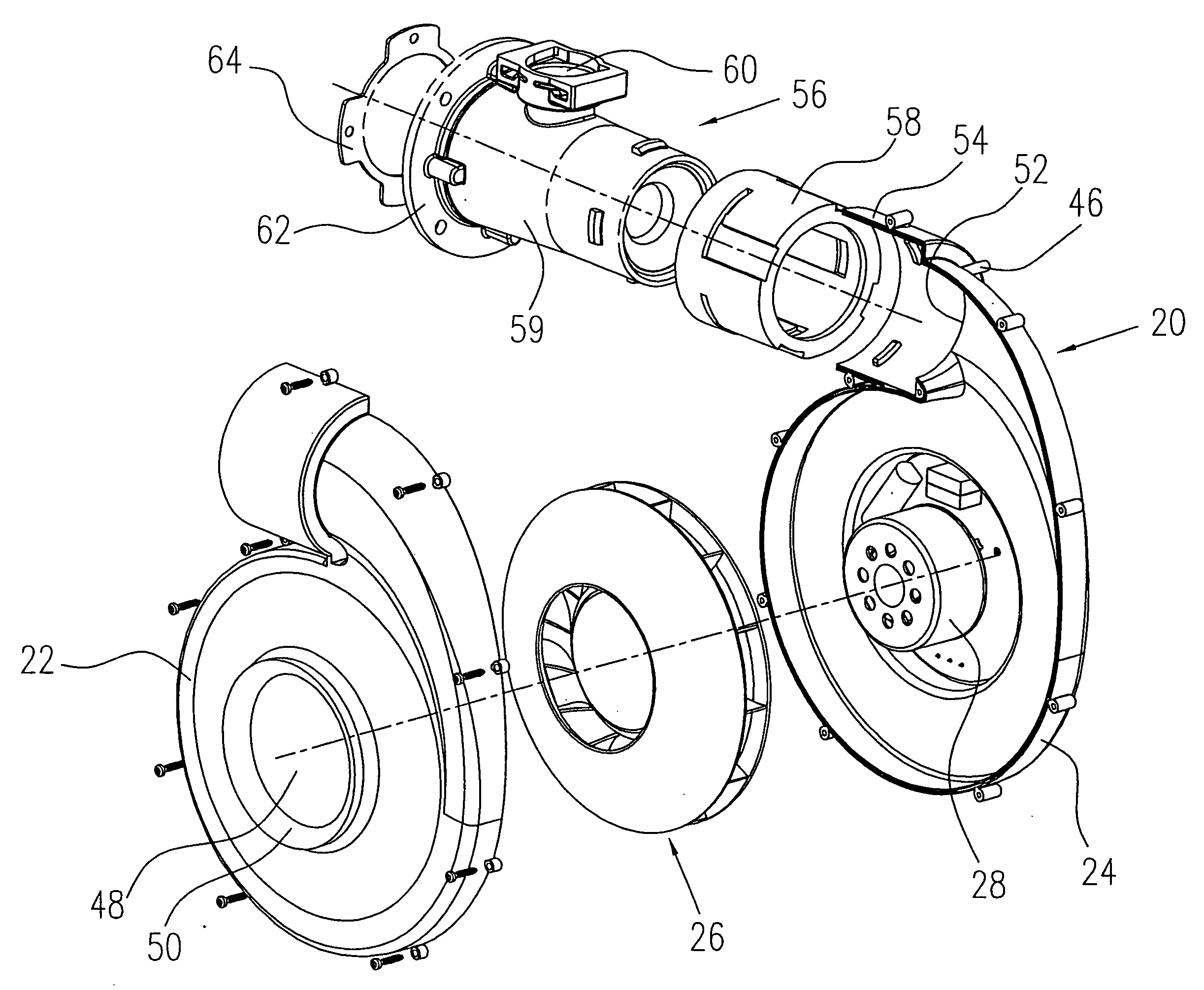
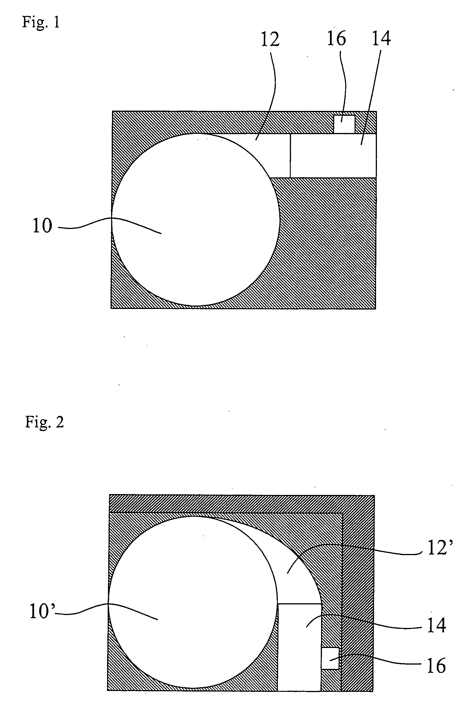
[0034]FIG. 1 schematically shows a fan housing 10 for a gas burner system according to the prior art whose air outlet tube 12 is coupled to a downstream venturi device 14 for the purpose of supplying combustion gas. The air outlet tube 12 extends tangentially away from the fan housing 10, its aperture also is lying on a plane tangential to the fan housing. A similar arrangement is also shown, for example, in the above mentioned U.S. Pat. No. 5,839,891.

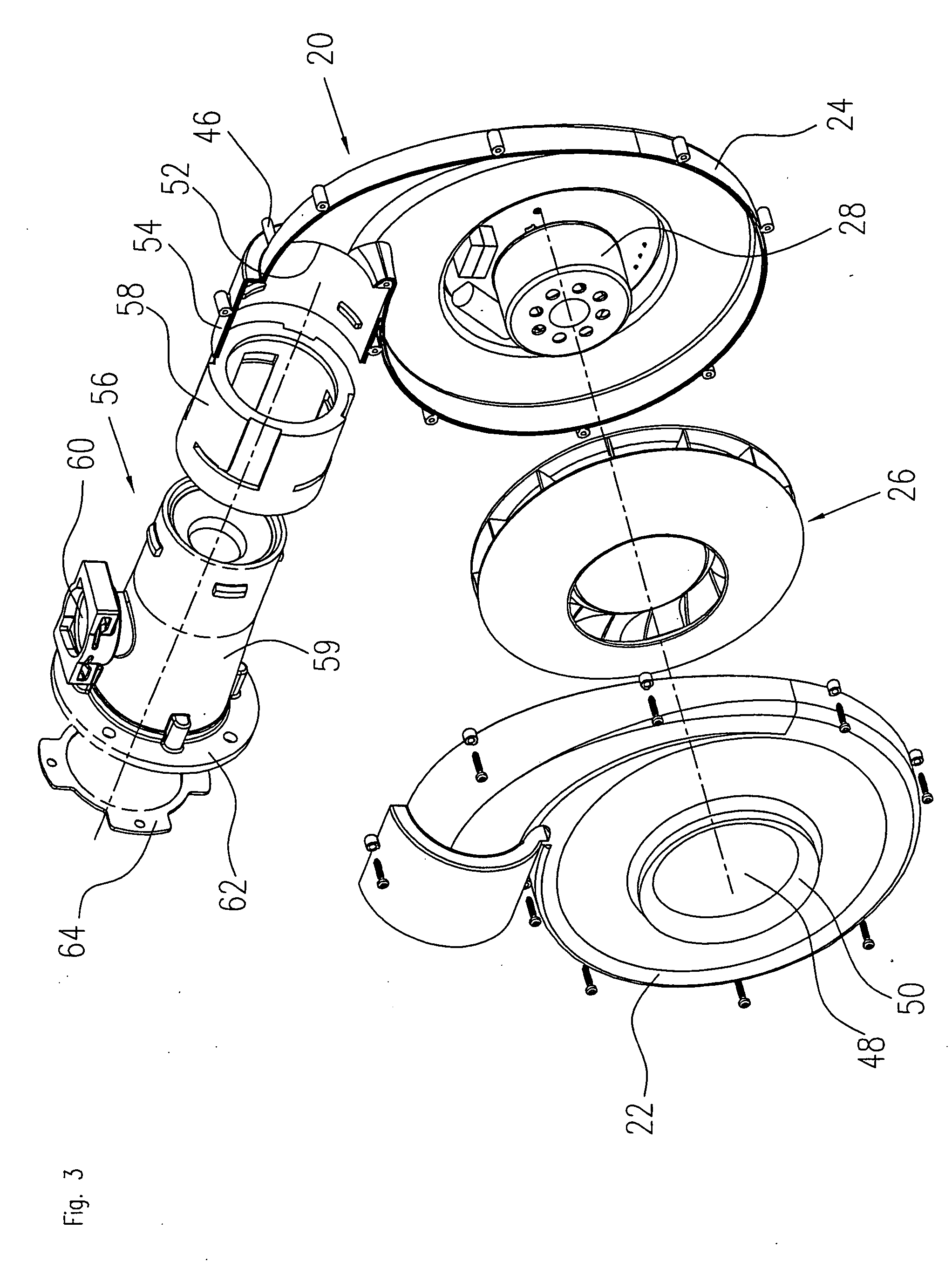
[0035]FIG. 2 schematically shows a fan for a gas burner system according to the invention that is coupled to an identical venturi device. In FIG. 2, the fan is represented by a fan housing 10 having an air outlet tube 12. According to the invention, the air outlet tube 12 of the fan housing 10 widens like a snail shell towards the outflow side of the fan, the aperture of the air outlet tube 12 lying on a plane that extends in a substantially radial manner to the fan housing 10. This makes it possible to dispose the venturi device 14 in...


PUM


Abstract

A fan for a gas burner system where at the outflow side of the fan a combustion gas is fed in, in order to form a flammable mixture of gas and air, the fan comprising a spiral-shaped fan housing having a rotational axis and an air outlet; the air outlet of the fan housing widening like a snail shell towards the outflow side of the fan; an impeller that is arranged concentric to the rotational axis in the interior of the fan housing; and an electric motor for driving the impeller, which is integrated at the center of the impeller.

Description

FIELD OF THE INVENTION [0001]The invention concerns a fan for a gas burner system where at the outflow side of the fan a combustion gas is fed in, in order to form a flammable mixture of gas and air.BACKGROUND OF THE INVENTION [0002]This kind of fan is known, for example, from EP 1 091 171 A1. This document describes a fan burner that can generate a homogeneous air flow. The fan burner comprises a fan housing having a spiral-shaped channel and an approximately perpendicular deflector making it possible to mount a burner housing at the aperture of the spiral-shaped channel lateral to the fan housing. The burner housing is located on the same side of the fan casing as an external drive for a radial impeller of the fan. Due to the deflector, which is turned towards the side of the electric motor, the burner is seated in the free space above the electric motor of the fan, thus making it possible to minimize the overall size of the device.[0003]U.S. Pat. No. 5,839,891 describes a gas bur...

Claims


Application Information

Patent Timeline
Patent Type & Authority Applications(United States)
IPC IPC(8): F04D29/60F04D29/08
CPCF23D14/02F23L5/02F23D14/36
Inventor ELSAESSER, ALEXANDERBREIER, ANTONGLATZ, KARL-HEINZ
Owner MINEBEAMITSUMI INC
Why Eureka
Try Eureka