Electrospraying/electrospinning array utilizing a replacement array of individual tip flow restriction

a technology of electrospinning array and individual tip, which is applied in the direction of spray nozzles, coatings, filament/thread forming, etc., can solve the problems of inability to feed pressurized fluid or a single positive displacement pump, unstable flow of liquid into the electrospinning orifice, etc., to facilitate the use of as many spraying tips and facilitate electrohydrodynamic spraying

Inactive Publication Date: 2008-06-05
DROPLETECH LLC
View PDF3 Cites 39 Cited by
  • Summary
  • Abstract
  • Description
  • Claims
  • Application Information

AI Technical Summary

Benefits of technology

[0009]In FIG. 3, we have added a series resistance, Rth, 104, to the circuit of FIG. 1 to, thereby, produce the V-I characteristics shown in FIG. 4. Note that the maintenance of a Ix2, 107, value by altering V is much more stable as V or the diode characteristics vary. In the spinning analogy, a series impedance added to the liquid flow path will facilitate electrohydrodynamic (EHD) spraying or spinning, which is much less sensitive to hydrostatic pressure, P, the E field at the spraying tip, or even the liquid parameters.
[0010]The present disclosure, therefore, is an Electrospinning or Electrospraying Array design that facilitates using as many spraying tips (J in number) as are required for production deposition. Each tip does not require a separate positive displacement pump or local field adjustment to balance between dripping and spinning or spraying. The present invention accomplishes flow matching for each tip through the use of J “Flow Constraining Resistances” (FCR), wherein the flow from a (preferably) common, pressurized fluid into each tip (n) is individually constrained to a flow rate, Fn. Providing nearly equal Flow Constraining Resistances to the individual flows, F1 through FJ, thereby, provides nearly equal flow into each of the J tips in the array. Once the flow rate is established by placing a common designed FCR in each orifice flow path, the Taylor cone spinning or spraying for all n orifices may be adjusted by varying one or more of the following: the electrostatic field, the physical properties of the liquid, or the pressure of the common liquid pool. No individual orifice adjustments are required once acceptable global parameters are established.

Problems solved by technology

If a positive displacement liquid tip flow is not provided individually to each spinning needle, the flow of liquid into the electrospinning orifices may be quite unstable.
In order to reach commercial deposition rates, the inventor envisions the need for thousands of spraying orifices comprising an “Electrospinning Array”—the use of individual positive displacement pumps becomes impractical when this many tips are employed.
It is the inventor's opinion that a single pressurized fluid or a single positive displacement pump cannot feed a practical large spinning array consisting of many individual tubes, which are otherwise unrestricted in their flow.
This is opined because the flow rate of each individual unrestricted tip is inherently unstable vis-à-vis its neighbor tube.
This in turn affects the flow (effective pressure) into other tips and, thus, the instability is maintained.
The teachings of Kim and Park, thereby, result in a complicated head, which contains many fluid flow paths, many flow adjustments, and precision machined parts to simply keep the drippings from reaching the product.
No claims are made concerning this path and it would be most difficult to form (drill) a working capillary having appropriate length to diameter ratios.

Method used


Image

  • Electrospraying/electrospinning array utilizing a replacement array of individual tip flow restriction
  • Electrospraying/electrospinning array utilizing a replacement array of individual tip flow restriction
  • Electrospraying/electrospinning array utilizing a replacement array of individual tip flow restriction

Examples


example 1

Fibrous or Micro Pore Sheet Flow Restrictor

[0035]FIG. 6 depicts a portion of a spinning array (here using tubes 6 of about 2 mm inside diameter and about 1″ apart to minimize electrostatic interactions), wherein a fibrous sheet, 20, restricts flow into each of the spraying tips. Using 24-Pound Bond paper as the fibrous sheet, we obtained a consistent flow for an water based fluid having a viscosity of μ=6.1 poise, as follows:[0036]14 psi 0.96 uL / min / tip

Using filter paper (two layers of #4 Whatman Qualitative Brand catalog #1004150) as the fibrous sheet and a water based fluid having a viscosity of μ=6.1 poise, we obtained a consistent flow, as follows:

1 psi10 uL / min / tip5 psi31 uL / min / tip10 psi 69 uL / min / tip

[0037]Note, that the flow is measured by calculation after observing the time necessary to form a hemispherical droplet having the spraying orifice diameter (with the electrostatic field off). The high restriction to fluid flow caused by the fibrous sheet restrictor causes the flo...

example 2

Pinhole Replaceable Sheet

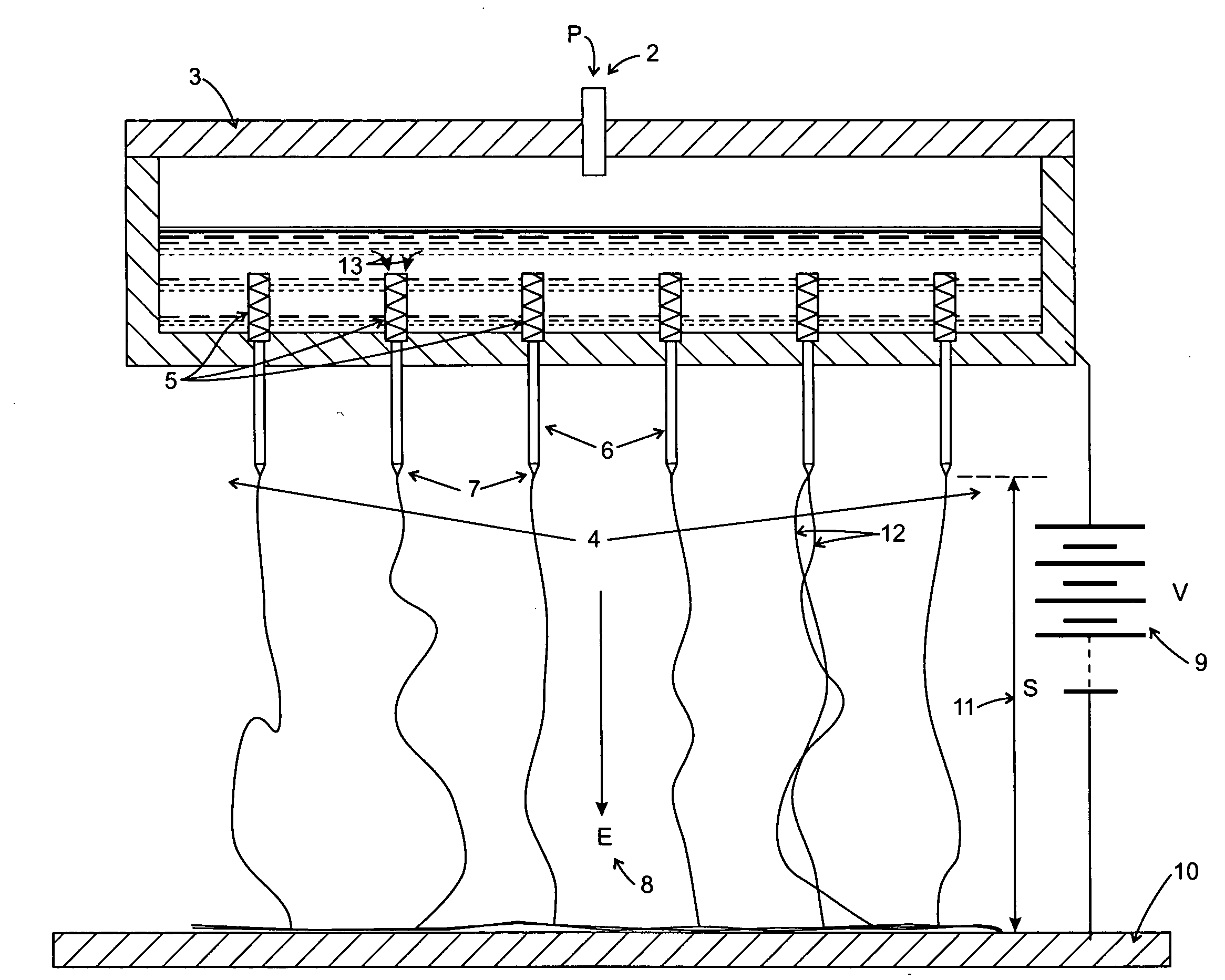
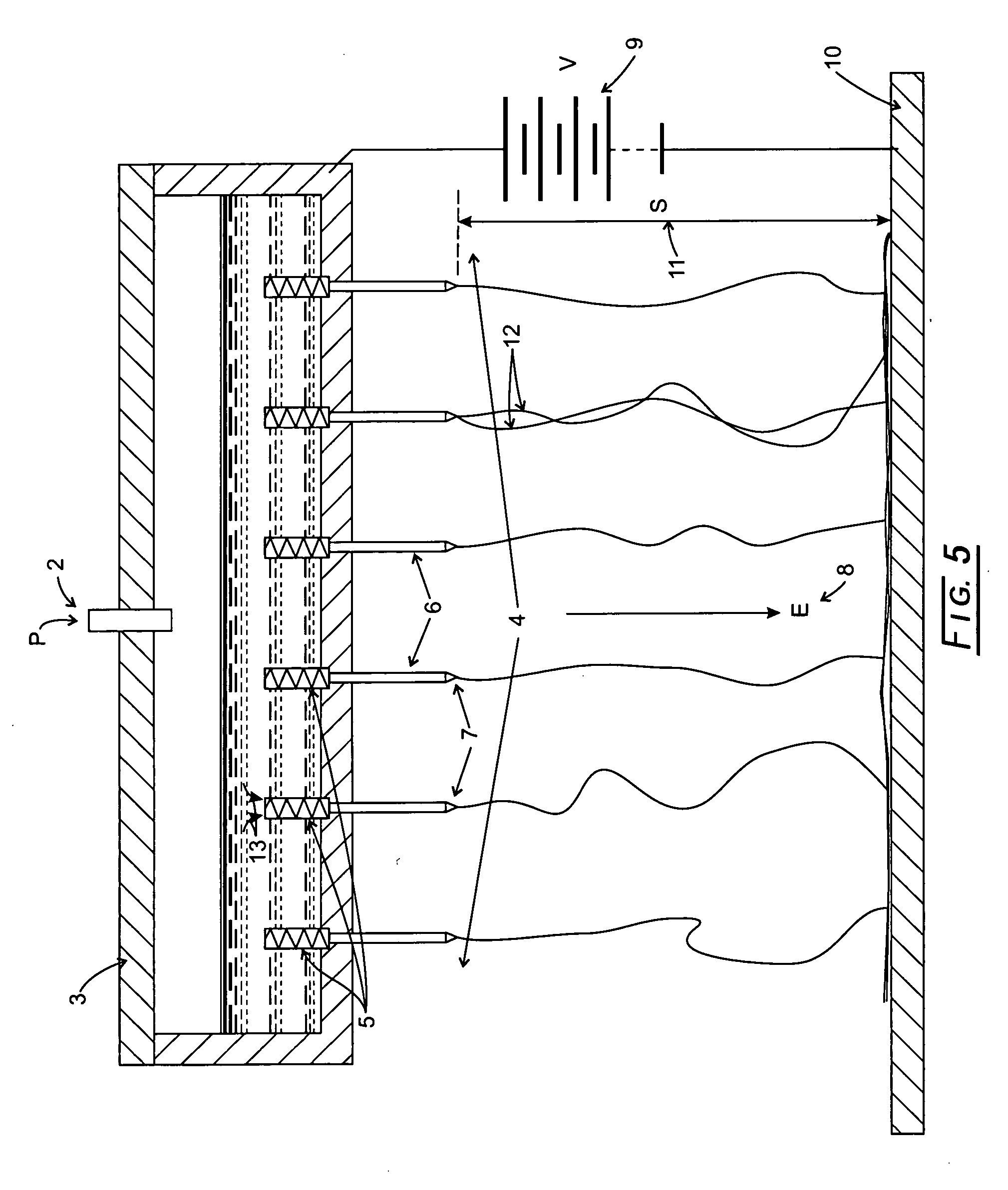
[0043]We propose the use of a small orifice, radius r or diameter d, preferably in a thin, impermeable, and replaceable sheet. This inventive flow restriction enables the spinning or spraying array to utilize liquids, which may contain small particulates.

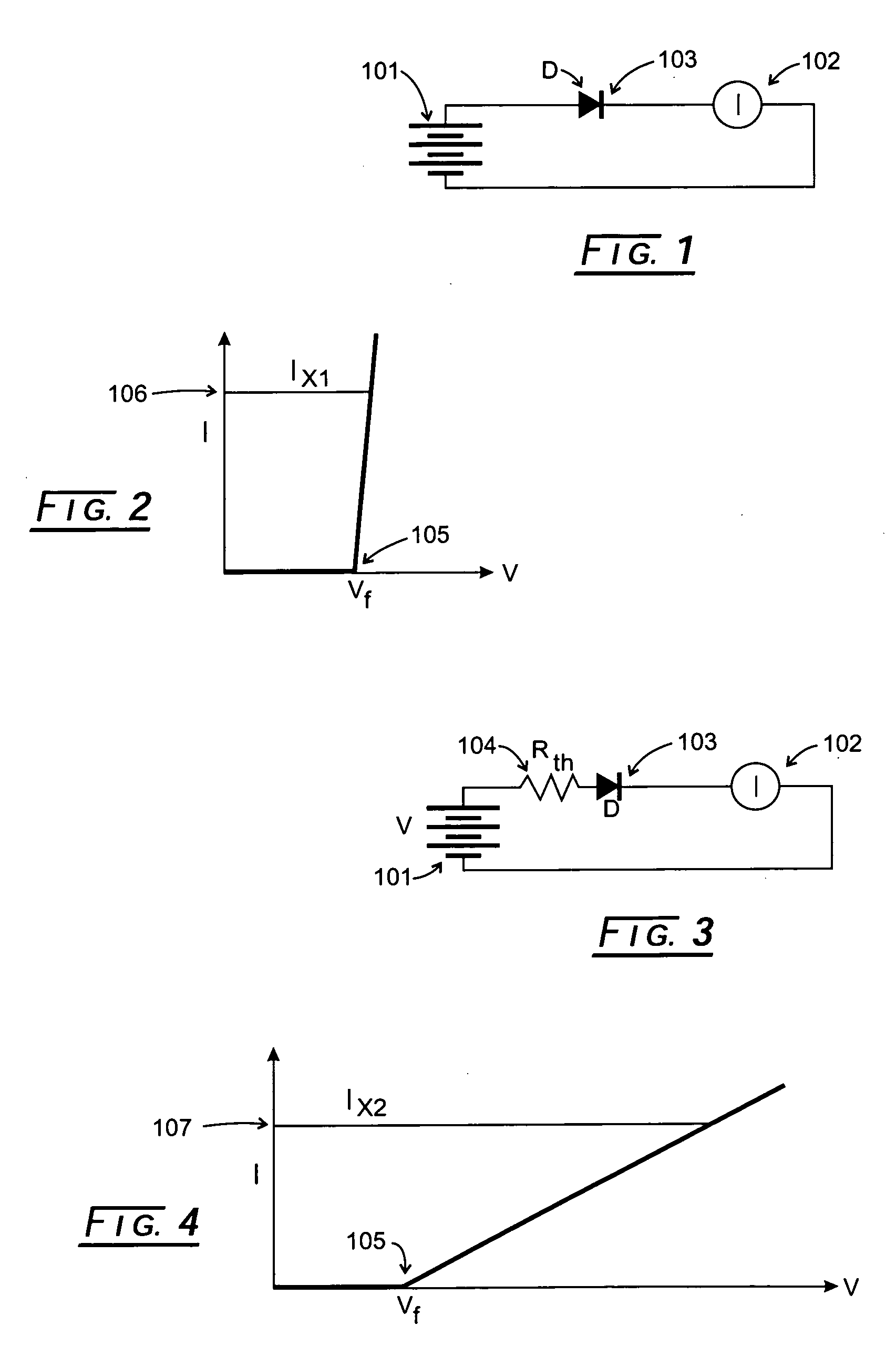
[0044]If the liquid has very low viscosity (say, less than about 10 centipoises), we can use the kinetic energy conservation to show that the flow volume V through such a pinhole is proportional to both the square of the orifice radius and the square root of the liquid pressure across the orifice. The flow also is inversely proportional to the square root of the liquid's viscosity, to wit:

V=πr2√(2P / μ)

We find experimentally that all liquids, which electrospin well into fibers, have viscosities above about 100 centipoises. For these more viscous liquids, the above-mentioned equation does not correctly predict the orifice flow. A much closer prediction to the orifice flow may be obtained using the following cap...


PUM

PropertyMeasurementUnit
inner diameteraaaaaaaaaa
diameteraaaaaaaaaa
diameteraaaaaaaaaa

Abstract

An electrohydrodynamic spraying or spinning deposition system, which includes a common source of pressurized liquid within a manifold, and an array of 2 or more spraying tips, each tip being fed from the common source of pressurized liquid to create a liquid flow path. An individual flow impedance device is disposed within each tip's individual liquid flow path from the pressurized liquid source into each spraying tip. The individual flow impedance devices are disposed within a replaceable sheet, which can be easily cleaned or changed to accommodate the instance liquid viscosity and composition. A high voltage source is applied to create a high voltage potential applied between the tip array and a deposition surface.

Description

CROSS-REFERENCE TO RELATED APPLICATIONS[0001]NoneSTATEMENT REGARDING FEDERALLY SPONSORED RESEARCH[0002]Not applicable.BACKGROUND OF THE INVENTION[0003]The present invention generally relates to the production of small or so-called “nano” fibers or droplets, which may be “spun” as fibers or “sprayed” as droplets by applying high electrostatic fields to liquid filled spraying tips, producing a Taylor cone at the tip opening. Thandavamoorthy Subbiath, G. S. Bhat, R. W Tock and S. S. Ramkumar, in the article, “Electrospinning of Nanofibers”, Journal of Applied Polymer Science, Vol. 96, 557-569 (2205), Wiley Periodicals, Inc., is instructive in this field. As the aforementioned article points out at page 561, there has been a debate on the potential and practicality of scaling up the technology to produce nanofibers at deposition rates required for commercial application.[0004]Much of the reported basic R&D on the electrospinning of nanofibers has utilized a single spraying tube (typical...

Claims


Application Information

Patent Timeline
Patent Type & Authority Applications(United States)
IPC IPC(8): B05D1/04B05B5/025D04H1/728
CPCB05B1/14B05B5/025D01D5/0069D01D1/09B05B5/0255
Inventor ROBERTSON, JOHN A.SCOTT, ASHLEY STEVE
Owner DROPLETECH LLC
Why Eureka
Try Eureka