Polishing method for extreme ultraviolet optical elements and elements produced using the method

a technology of ultraviolet light and ultraviolet light, applied in the field of polishing silicatitania glass elements, can solve the problems of high surface roughness, material with differential stress, and material uniformity affecting the effect of material removal during polishing, and achieve the effect of high flow ra

Inactive Publication Date: 2008-06-05
CORNING INC
View PDF4 Cites 26 Cited by
  • Summary
  • Abstract
  • Description
  • Claims
  • Application Information

AI Technical Summary

Problems solved by technology

Although these small, localized glass chemistry deviations do not affect bulk CTE, the uniformity of material removal during polishing can be affected due to the fact that these areas of localized stress can be susceptible to differential reaction in aqueous environments.
However, materials with differential stress (for example, silica-titania and other “doped” glasses) can be sensitive to ceria's combined chemical-mechanical material removal mechanism.
As a result, high surface roughness can occur.
However, it is nearly impossible to extract or form such pieces without having at least some striae break the surface.
When standard polishing processes are used to polish the piece into the desired optical element it has been found that these standard methods result in finished pieces that have mid-spatial frequency (“MSF”) topographical defects that have been found to perfectly coincide with varying TiO2 level in the glass (the difference in TiO2 between different layers), and thus the stress between discrete striae layers.
If the pieces are intended as for use as a mask materials for EUVL, these striae-induced MSF defects are a limiting factor for the qualification of any polished part.

Method used


Image

  • Polishing method for extreme ultraviolet optical elements and elements produced using the method
  • Polishing method for extreme ultraviolet optical elements and elements produced using the method
  • Polishing method for extreme ultraviolet optical elements and elements produced using the method

Examples


Embodiment Construction

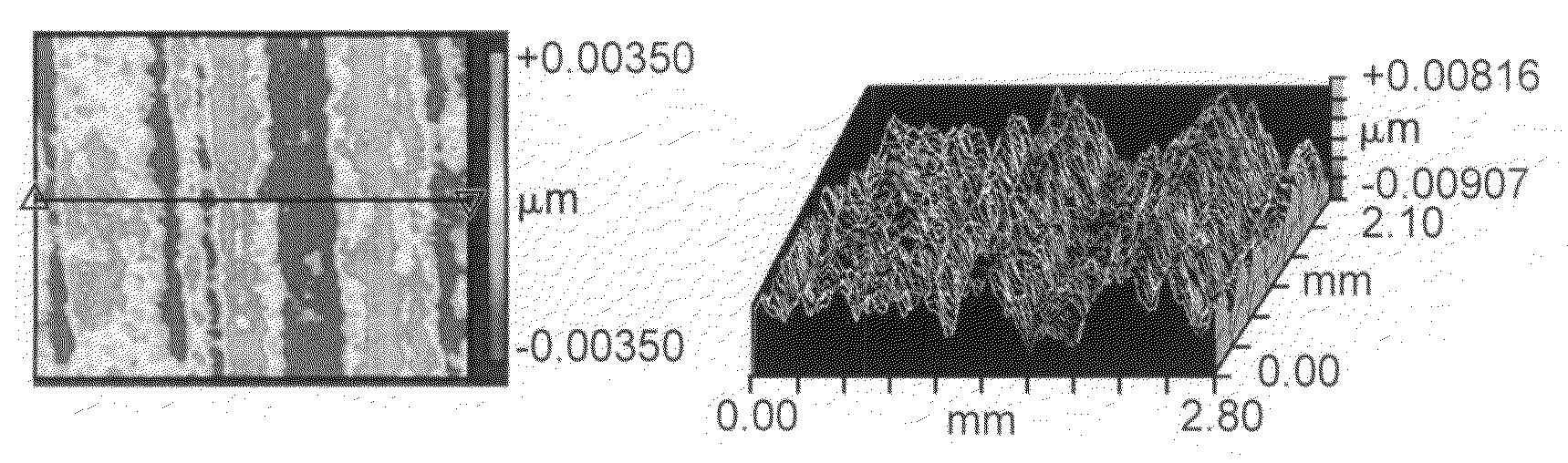
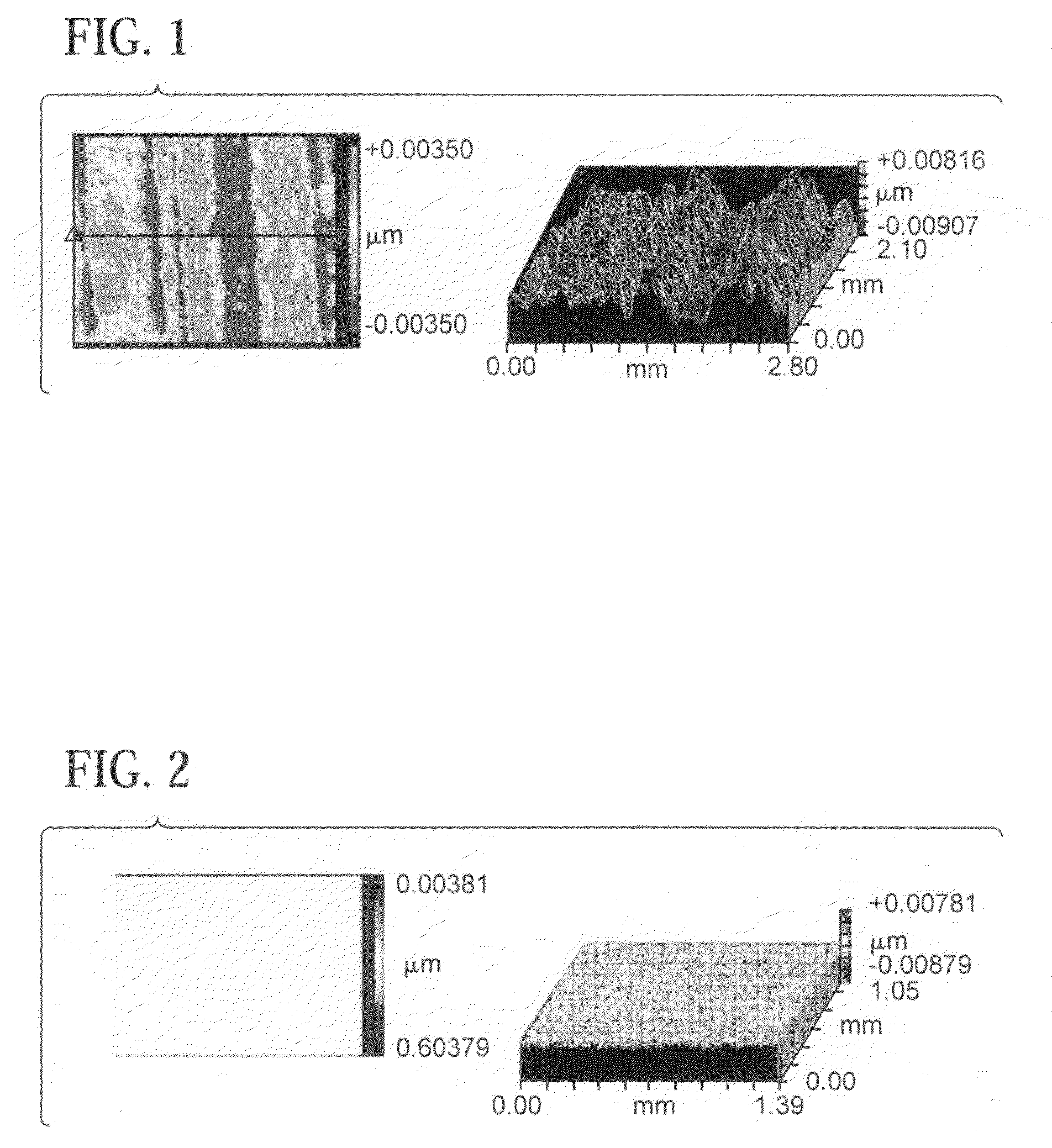
[0020]As has been mentioned above, the standard methods of polishing ultra-low expansion glass surfaces, and in particular silica-titania glass surfaces, using “low” slurry flow rates can produce surfaces that have sufficient roughness such that they are unsuitable for EUVL applications. Ultra-low expansion glasses are those having a CTE of less than 0±30×10−9 / ° C. (0±30 ppb / ° C.) as exemplified by ULE® glass from Corning Incorporated. As used herein the term “ULE” without the trademark symbol is used to signify “ultra-low expansion glass” generally, and in particular silica-titania glass and glass surfaces, that can be polished using the invention to produce optical elements with finished surfaces having extremely low mid-spatial frequency (“MSF”) and extremely low high-spatial frequency (“HSF”) roughness values. Striae in ULE is well recognized as a limiting factor in attainment of surfaces planar in the MSF range due to preferential material removal at locations of high stress be...


PUM

PropertyMeasurementUnit
roughnessaaaaaaaaaa
roughnessaaaaaaaaaa
roughnessaaaaaaaaaa

Abstract

The invention is directed to polished glass substrates suitable for extreme ultraviolet lithography. The elements are silica-titania glass elements having a coefficient of thermal expansion of 0±30×10−9 / ° C. or less, and containing 5-10 wt. % titania. The polished elements have a mid-spatial frequency peak-to-valley roughness of <10 nm and a high-spatial frequency roughness of <0.20 nm average roughness. The invention is further directed to a method of for producing optical elements suitable for extreme ultraviolet lithography (“EUVL”), the method having at least the steps of providing a glass substrate in the shape of the desired optical element and polishing the shaped substrate using a high abrasive slurry flow rate of >2.0 ml / cm2 / min. Generally the flow rates are in the range of 2.0-10 ml / cm2 / min. Glass substrates suitable for extreme ultraviolet lithography element have a coefficient of thermal expansion of 0±30×10−9 / ° C. or less. A particular glass suitable for EUVL use is silica-titania glass containing 5-10 wt. % titania.

Description

PRIORITY[0001]This application claims the priority of U.S. Provisional Application No. 60 / 861,922, filed Nov. 30, 2006, and titled “A POLISHING METHOD FOR EXTREME ULTRAVIOLET OPTICAL ELEMENTS AND ELEMENTS PRODUCED USING THE METHOD.”FIELD OF THE INVENTION[0002]The invention is directed to polished silica-titania glass elements, and in particular to polished silica-titania glass elements suitable for use in extreme ultraviolet lithography, and to a polishing method for making such elements.BACKGROUND OF THE INVENTION[0003]Glass materials such as silica-titania (SiO2—TiO2) glasses that are used for extreme ultraviolet lithography (“EUVL”) elements have been produced by various methods. In some of these methods, for example the flame hydrolysis method, striae can occur during the laydown process, resulting in discrete layers of silica-titania glass that can have a variation of ±0.1 wt. % TiO2. During cool-down from glass forming temperatures differential stress relaxation from the sligh...

Claims


Application Information

Patent Timeline
Patent Type & Authority Applications(United States)
IPC IPC(8): B24B1/00
CPCB24B13/00B82Y10/00B82Y40/00C03C3/04C03C19/00G03F1/08C03B2201/42G03F7/70958G21K1/062G21K2201/067C03B2201/31C03B2201/32G03F1/24
Inventor ARSERIO, GREGORY JOHNSABIA, ROBERTSYLVIA, BRIAN DANIEL
Owner CORNING INC
Why Eureka
Try Eureka