Spectral polarizing tomographic dermatoscope

a dermatoscope and spectral polarization technology, applied in the field of skin, mucosa and cervical tissues, can solve the problems of obfuscating much of the subsurface structure of interest, lack of foresight and the ability to perform satisfactory self-examination, and poor preparation of non-dermatologist physicians to recognize and diagnose melanomas

Inactive Publication Date: 2008-06-05
ALFANO ROBERT R +3
View PDF2 Cites 29 Cited by
  • Summary
  • Abstract
  • Description
  • Claims
  • Application Information

AI Technical Summary

Benefits of technology

[0018]Therefore, according to one aspect of the invention, there is provided an apparatus suitable for use in examining skin, mucosa and cervical tissues for the purpose of detecting cancer and precancerous conditions therein, said apparatus comprising (a) first illuminating means for illuminating an object with polarized light of a first color; (b) second illuminating means for illuminating an object with polarized light of a second color, said second color being different from said first color; (c) a control coupled to each of said first illuminating means and said second illuminating means to permit selective actuation of said first illuminating means and said second illuminating means; (d) a light detector for outputting an electrical signal in response to light incident thereonto; (e) an adjustable polarizer positioned between said light detector and the illuminated object; (f) optics for imaging light emitted from the illuminated object onto said light detector (or (i) a confocal optical imaging system for filtering undesired light and image surface and subsurface information from the illuminated object onto said light detector or (ii) a mechanically or electronically movable platform that houses the optical imaging system to bring the imaging layer of interest (e.g., layer 1, layer 2, or layer n) to the focal imaging plane while keeping a fixed focal distance f1 or (iii) a mechanically or electronically retractable optical housing to bring the imaging layer of interest (e.g., layer 1, layer 2, or layer n) to the focal imaging plane while keeping the optical imaging system fixed); (g) a computer for processing the output from said light detector; (h) means for transmitting the output from said light detector to said computer; and (i) a display for displaying the results of said processing from said computer. The display may be located proximally relative to said computer and connected directly thereto or may be located remotely relative to said computer and connected to said computer, for example, via modem and a second computer.

Problems solved by technology

Despite the fact that approximately 1 in 87 Americans will be diagnosed with melanoma during his / her lifetime, the public, on balance, lacks the foresight and the ability to perform satisfactory self-examinations.
In addition, the examination of skin by primary care, non-dermatologist physicians is uncommon, and such non-dermatologist physicians are poorly prepared to recognize and to diagnose melanomas.
One problem associated with visually inspecting skin with the unaided eye or with a magnifying glass is that much of the light used to illuminate the skin being examined is diffusely reflected by the outermost surface of the skin, thereby obfuscating much of the subsurface structures of interest.
Another problem associated with visually inspecting skin with the unaided eye or with a magnifying glass is that certain lesions are too small to be readily detected.
Although, as explained above, conventional dermatoscopes provide a measure of improvement over the unaided eye or a magnifying glass, conventional dermatoscopes still suffer from certain drawbacks.
One such drawback is that the operator must bring his / her face down into proximity with the dermatoscope and, by extension, must bring his / her face down into proximity with the patient's skin.
Another such drawback is that no permanent record of the observation of the skin is taken as the skin is viewed directly by the operator.
Also, no telemedicine information can be relayed for expert diagnosis and advice.
Another problem associated with the examination of skin, whether said skin is observed with the unaided eye or with the aid of a dermatoscope, is that the analysis of the observed image often requires the application of qualitative and / or poorly-defined criteria.
Such criteria may be judged differently by different individuals, thereby leading to a lack of uniformity in diagnosis among various observers.
As can readily be appreciated, one disadvantage associated with dermatoscopes of the types described above is that mineral oil, solvent or the like must be applied to the patient's skin in order to minimize diffuse reflection at the outermost layer of skin and, in so doing, to render the skin more transparent to white lamp light.
Another disadvantage associated with existing dermatoscopes is their inability to distinguish subsurface imaging information.

Method used


Image

  • Spectral polarizing tomographic dermatoscope
  • Spectral polarizing tomographic dermatoscope
  • Spectral polarizing tomographic dermatoscope

Examples


first embodiment

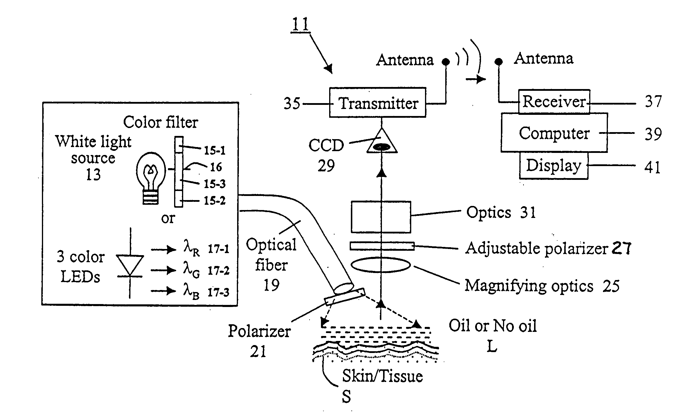
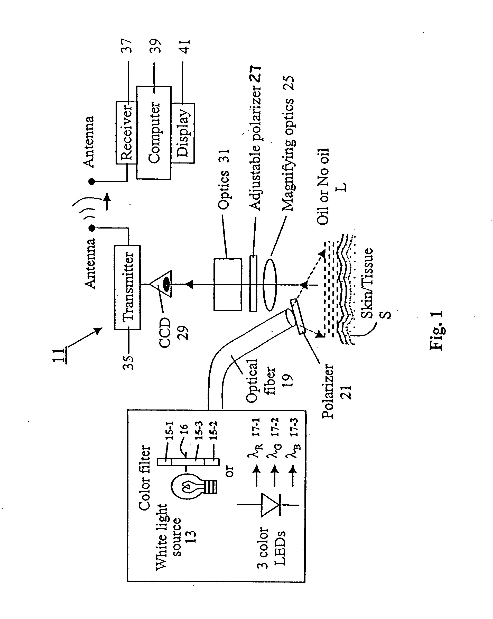
[0029]Referring now to FIG. 1, there is shown a schematic diagram of an apparatus constructed according to the teachings of the present invention for use in examining objects, said apparatus being represented generally by reference numeral 11. Apparatus 11 may be used, for example, to examine an object, such as skin, mucosa and cervical tissues for the purpose of detecting cancer and precancerous conditions therein or to examine a solid or structured object for the purpose of detecting defects therein.

[0030]Apparatus 11 comprises first illuminating means for illuminating an object with polarized light of a first wavelength. The light of a first wavelength may be in the ultraviolet, visible or near-infrared portions of the spectrum. In the present embodiment, said first illuminating means preferably comprises a white light source 13, such as a white light lamp emitting 2.5 mW, and a filter 15-1 selective for light of a first color. Filter 15-1 may be, for example, a narrow band filte...

second embodiment

[0038]Referring now to FIG. 3, there is shown a schematic diagram of an apparatus constructed according to the teachings of the present invention for use in examining objects, said apparatus being represented generally by reference numeral 51.

[0039]Apparatus 51 is similar in many respects to apparatus 11, the principal differences between the two apparatuses being that transmitter 35 and receiver 37 of apparatus 11 are replaced in apparatus 51 with a cable 53 coupled at one end to light detector 29 and at the other end to computer 39 for transmitting the output of detector 29 to computer 39. Apparatus 51 further includes a housing 55 for housing the other components of apparatus 51. Display 41, which may be, for example, an LCD unit, is mounted in an opening 57 provided in housing 55 so as to be viewable by an operator. The image information processed by computer 39 may be stored in computer 39 and / or may be stored on removable compact memory cards 60 removably mounted in computer 3...

third embodiment

[0040]Referring now to FIG. 4(a), there is shown a schematic diagram of an apparatus constructed according to the teachings of the present invention for use in examining objects, said apparatus being represented generally by reference numeral 101.

[0041]Apparatus 101, which is functionally similar in many respects to apparatus 11, includes a hand-held housing 103. Housing 103 is gun-shaped and includes a handle portion 105 and a barrel portion 107. The front end of barrel portion 107 is open, and a glass cover 109 is mounted therein. For reasons to be discussed below, a portion 108 of barrel portion 107 is expandable / retractable in the directions indicated by double headed arrow 110.

[0042]Apparatus 101 additionally comprises a red LED 111-1, a green LED 111-2, a blue LED 111-3, and a white LED 111-4, all of which are disposed within handle portion 105 of housing 103 and all of which are electrically connected to a battery 113 also disposed within handle portion 105 of housing 103. A ...


PUM


Abstract

An apparatus for use in examining an object, such as skin, mucosa and cervical tissues for detecting cancer and precancerous conditions therein. In one embodiment, the apparatus includes a gun-shaped housing having a handle portion and a barrel portion. The front end of the barrel portion is open, and a glass cover is mounted therein. LED's are disposed within the handle portion. A manually-operable switch for controlling actuation of the LED's is accessible on the handle portion. An optical fiber is used to transmit light from the LED's through a first polarizer in the barrel portion and then through the glass cover to illuminate a desired object. Reflected light from the object is passed through a second polarizer, which is adjustably mounted in the barrel portion and which is preferably oriented to pass depolarized light emitted from an illuminated object, and is then imaged by optics onto a CCD detector. The detector is coupled to a wireless transmitter that transmits the output from the detector to a remotely located wireless receiver.

Description

CROSS-REFERENCE TO RELATED APPLICATIONS[0001]The present application is a continuation of U.S. patent application Ser. No. 10 / 610,339, filed Jun. 30, 2003, which in turn is a continuation-in-part of U.S. patent application Ser. No. 09 / 550,094, filed Apr. 14, 2000, now U.S. Pat. No. 6,587,711, which in turn claims the benefit under 35 U.S.C. § 119(e) of U.S. Provisional Patent Application Ser. No. 60 / 144,975, filed Jul. 22, 1999, all of the aforementioned patent applications being incorporated herein by reference.BACKGROUND OF THE INVENTION[0002]The present invention relates generally to the examination of skin, mucosa and cervical tissues for the purpose of detecting cancer and precancerous conditions and relates more particularly to a novel apparatus for use in performing examinations of the aforementioned types.[0003]Cutaneous melanoma is a disease of increasing clinical and economic importance, both in the United States and abroad. For this reason, the early detection of cancerou...

Claims


Application Information

Patent Timeline
Patent Type & Authority Applications(United States)
IPC IPC(8): A61B6/00A61B5/00A61B5/103
CPCA61B5/0059A61B5/0068A61B5/0073A61B5/0084A61B5/415A61B5/0013A61B5/4331A61B5/443A61B5/444A61B5/445A61B5/418
Inventor ALFANO, ROBERT R.BUDANSKY, YURYLUO, JINGCHENGZEVALLOS, MANUEL E.
Owner ALFANO ROBERT R
Why Eureka
Try Eureka