Method to Provide Slots in Pipes

a technology of pipes and slots, applied in the field of pipes providing slots, can solve the problems of high flexibility rate, low mechanical resistance, and inconvenient complex manufacturing, and achieve the effects of avoiding clogging of particulate materials, simple and fast operations, and more uniformity

Inactive Publication Date: 2008-06-12
PEGORETTI MARCOS ROGERIO
View PDF12 Cites 8 Cited by
  • Summary
  • Abstract
  • Description
  • Claims
  • Application Information

AI Technical Summary

Benefits of technology

[0011]One object of the present invention is to build pipes with slots that have a mixed transverse section, composed of a portion of parallel walls and a portion of divergent walls, continuously, to avoid clogging by particulate material.
[0012]It is also an object of the invention to make such slots by means of one single tool to guarantee that the walls are as smooth as possible to avoid the accumulation of particulate material.
[0013]These objects and other advantages are reached by means of a method to provide slots in pipes by using laser or plasma cutting equipment which assure that slots have the desired finish and configuration, by means of simple and fast operations, providing more uniformity and, at the same time, guaranteeing the structural resistance of the metal pipe.

Problems solved by technology

Some of them are made of wire systems, such as U.S. Pat. No. 4,550,778 and U.S. Pat. No. 4,821,800, which present the inconveniences of complex manufacturing; difficult introduction in the well (in horizontal wells, high flexibility rate is required); low mechanical resistance (screened pipes disrupt due to the low resistance of screens in complex route slotted wells, such as horizontal wells and those with high slope and angle).
On the other hand, the existing slotted systems, such as U.S. Pat. No. 4,526,230, have the inconveniences of disruption of external pipes and consequent loss of sand that acts as the filtering element, the increase in the concentration of impurities in the filtering element and the loss of efficiency during its working life.
Such machines and tools are generally very complex mechanically speaking and require large energy costs.
After some time, this configuration of walls causes slots to clog, since the particulate material settles there and no longer allows the oil to pass through.
This new kind of slot, called calestone, has the inconvenience of increasing the opening of the periphery during the working life of the pipe, due to loss of wall thickness by abrasion of the sand passing through the slot.
Therefore, the pipe loses the internal slot dimension and consequently loses the granular control of the sand.
This solution is made by means of molding, making the operation extremely costly, making the pipe structurally fragile and making its transportation difficult, besides the granular control problem previously mentioned.
This method has the inconvenience of the use of a laser beam, whose focal distance is zero, and this way creates a parallel slot with a single width, which is the minimum laser width, i.e. 0.1 mm.

Method used


Image

  • Method to Provide Slots in Pipes
  • Method to Provide Slots in Pipes
  • Method to Provide Slots in Pipes

Examples


Embodiment Construction

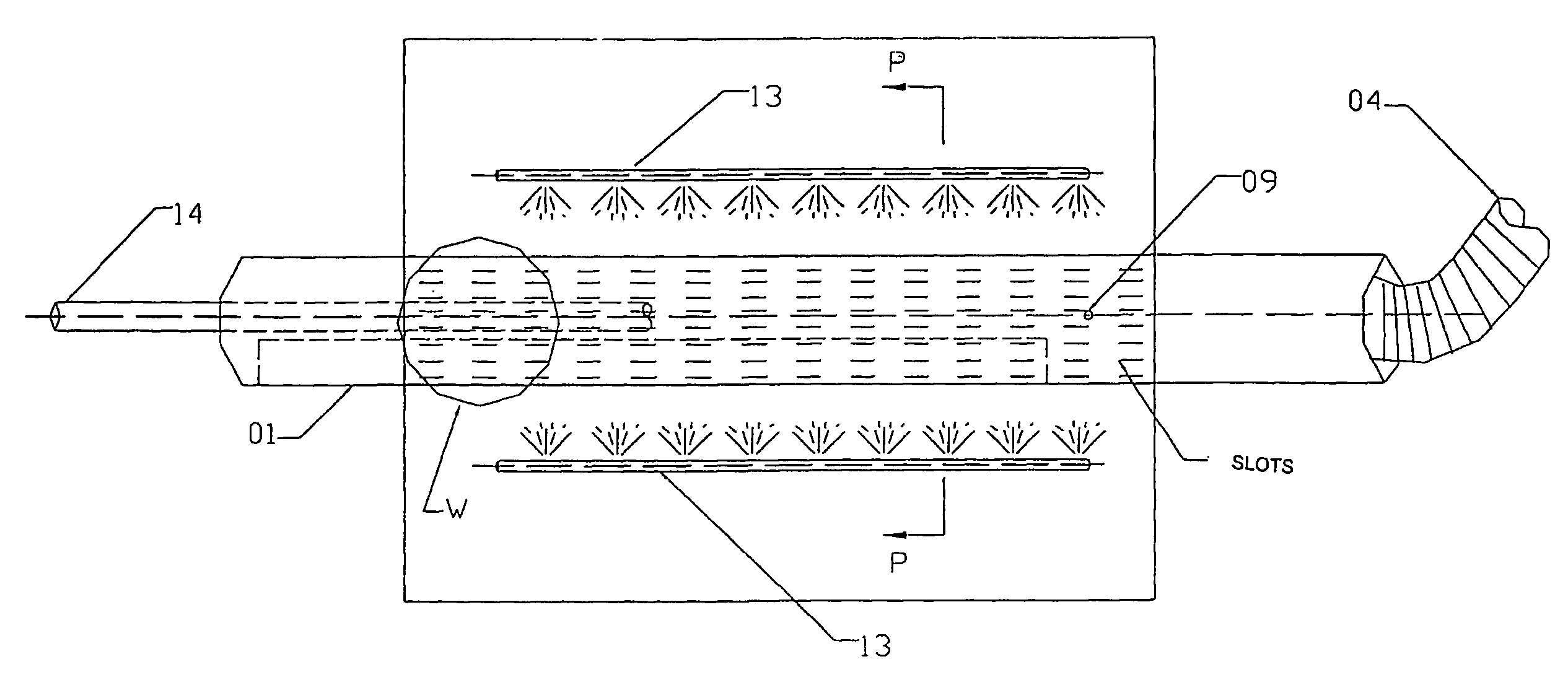
[0021]The method to provide slots in pipes, object of the present invention, consists of the following steps:

a) external cleaning of the pipe 1 with slag blasting to remove the protecting layer that comes from its manufacture or to remove the impurities due to its oxidation;

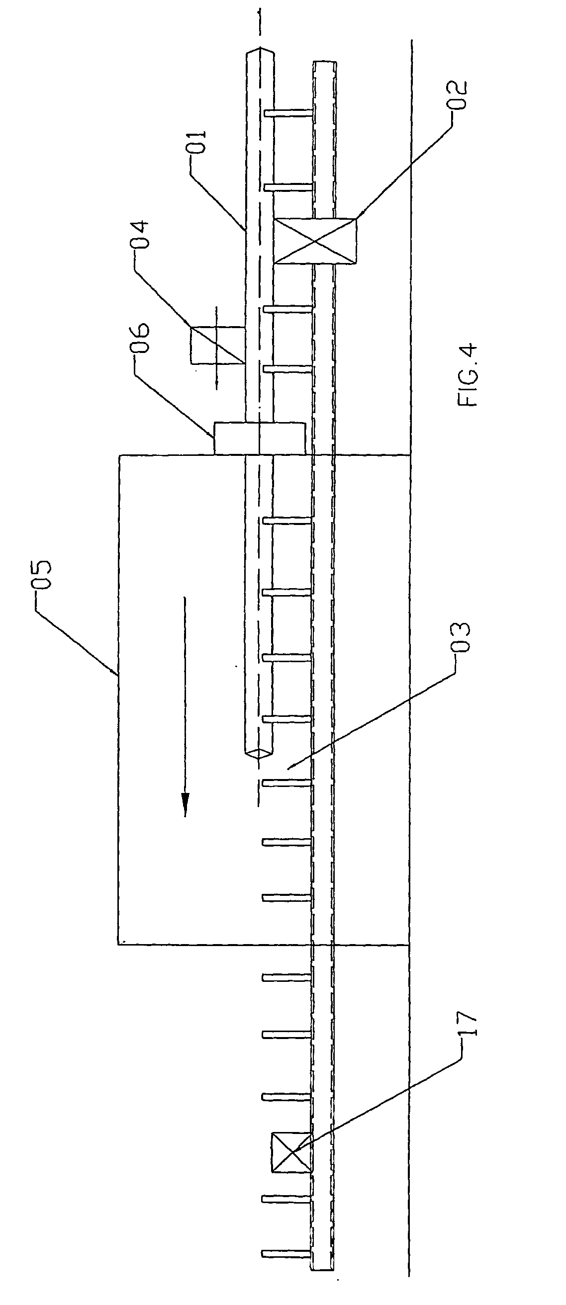
b) placing the pipe 1 on the receiving table by the set of motors 2 to be subsequently transferred to the cutting table 3, by means of motors 4;

c) positioning and fixation of the pipe in the cutting cabin 5 by tightening of the pneumatic rotating plate 6;

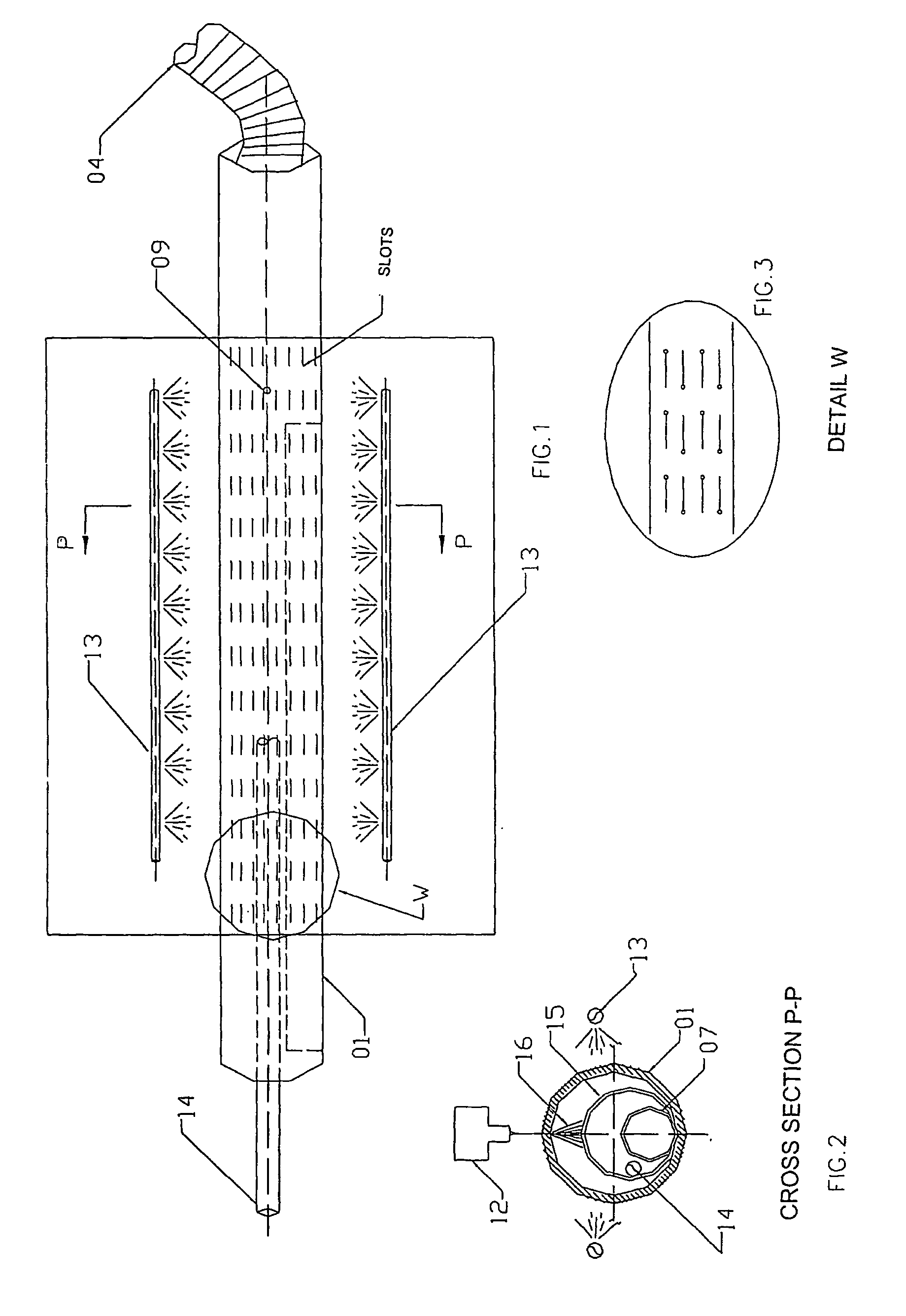
d) execution of the first sequence of slots in the pipe by laser or plasma, in a refrigerated environment, by making an initial hole with pre-defined power and subsequently opening the slot with determined length and thickness, according to the characteristics of the pipe, said slot having an initial parallel section and subsequently a divergent section;

e) angle rotation of the pipe by turning the rotating plate 6 to make the second sequence of slots, in the oppo...


PUM

PropertyMeasurementUnit
total thicknessaaaaaaaaaa
widthaaaaaaaaaa

Abstract

The present invention refers to a method to provide slots in pipes and, more specifically, to a method to provide slots in metal pipes used to extract oil or to form slotted lines, wherein said slots are specially designed to avoid the intake of impurities while pumping oil. More specifically, the method consists of the following steps: a) external cleaning of the pipe (1) with slag jetting to remove the protecting layer that comes from its manufacture or to remove the impurities due to its oxidation; b) placing the pipe (1) on the receiving table by the set of motors (2) to be subsequently transferred to the cutting table (3), by means of motors (4); c) positioning and fixation of the pipe in the cutting cabin (5) by screwing the pneumatic rotating plate (6); d) execution of the first sequence of slots in the pipe by means of laser or plasma, in a refrigerated environment, by making a first slot with pre-defined power and subsequently the opening of the slot with determined length and thickness, according to the characteristics of the pipe, with said slot having an initial section with parallel shape and subsequently with divergent section; e) angle rotation of the pipe by means of turning the rotating plate (6) to make the second sequence of slots, in the opposite direction of the first sequence and then successively on the whole perimeter of the pipe to meet the desired specification; f) removal of the sludge and impurities generated by the cut by the sleeves (7); g) internal cleaning of the slotted pipe with slag jetting; h) visual inspection of the slotted pipe to correct failures and possible imperfections with MIG soldering; and i) painting to provide a uniform visual aspect to the slotted pipe.

Description

FIELD OF THE INVENTION[0001]The invention refers to a method to provide slots in pipes and, more specifically, to a method to provide slots in metal pipes used to extract oil or to form slotted lines, wherein said slots are specially designed to avoid the intake of impurities while pumping oil.BACKGROUND OF INVENTION[0002]The oil industry uses a wide range of accessories, devices and equipment to perforate and extract oil, which are particularly important when dealing with perforations under water and in horizontal and vertical land wells.[0003]One of such devices is a pipe provided with perforations, usually called slotted line or slotted pipe, which is used to extract oil from horizontal and vertical wells. The pipe has in its design, a number of slots to allow the oil to pass through them, blocking the passage of particulate material found in the well or in the oil region to be exploited.[0004]Such pipes have various configurations. Some of them are made of wire systems, such as ...

Claims


Application Information

Patent Timeline
Patent Type & Authority Applications(United States)
IPC IPC(8): B23P15/16B21D28/28B23K10/00B23K26/00B23K26/08B23K26/38B26F1/31E21B29/08E21B43/08
CPCB23K9/173B23K10/00B23K26/0823B23K26/383Y10T29/496B23K26/421B23K2201/06E21B43/086B23K26/388B23K26/384B23K26/389B23K26/60B23K2101/06
Inventor PEGORETTI, MARCOS ROGERIO
Owner PEGORETTI MARCOS ROGERIO
Why Eureka
Try Eureka