
System And Method For Producing Water

a technology of system and method, applied in the direction of combustible gas purification/modification, lighting and heating apparatus, separation processes, etc., can solve the problems of severely impaired water dispensing capability of prior art air-to-water generating system, and less useful machines for most commercial and residential purposes, so as to maintain water quality

Inactive Publication Date: 2008-06-12
AQUA SCI INC
View PDF50 Cites 29 Cited by
  • Summary
  • Abstract
  • Description
  • Claims
  • Application Information

AI Technical Summary

Benefits of technology

[0010]The invention also provides a method for producing water that includes removing water from a first airflow using a first process which includes exposing at least some of the first airflow to a desiccant. This increases the water content of at least some of the desiccant. At least some of the desiccant having increased water content is introduced into a second airflow, thereby facilitating evaporation of water from the desiccant into the second airflow. This also increases water content of the second airflow. Water is then removed from the second airflow after its water content is increased.
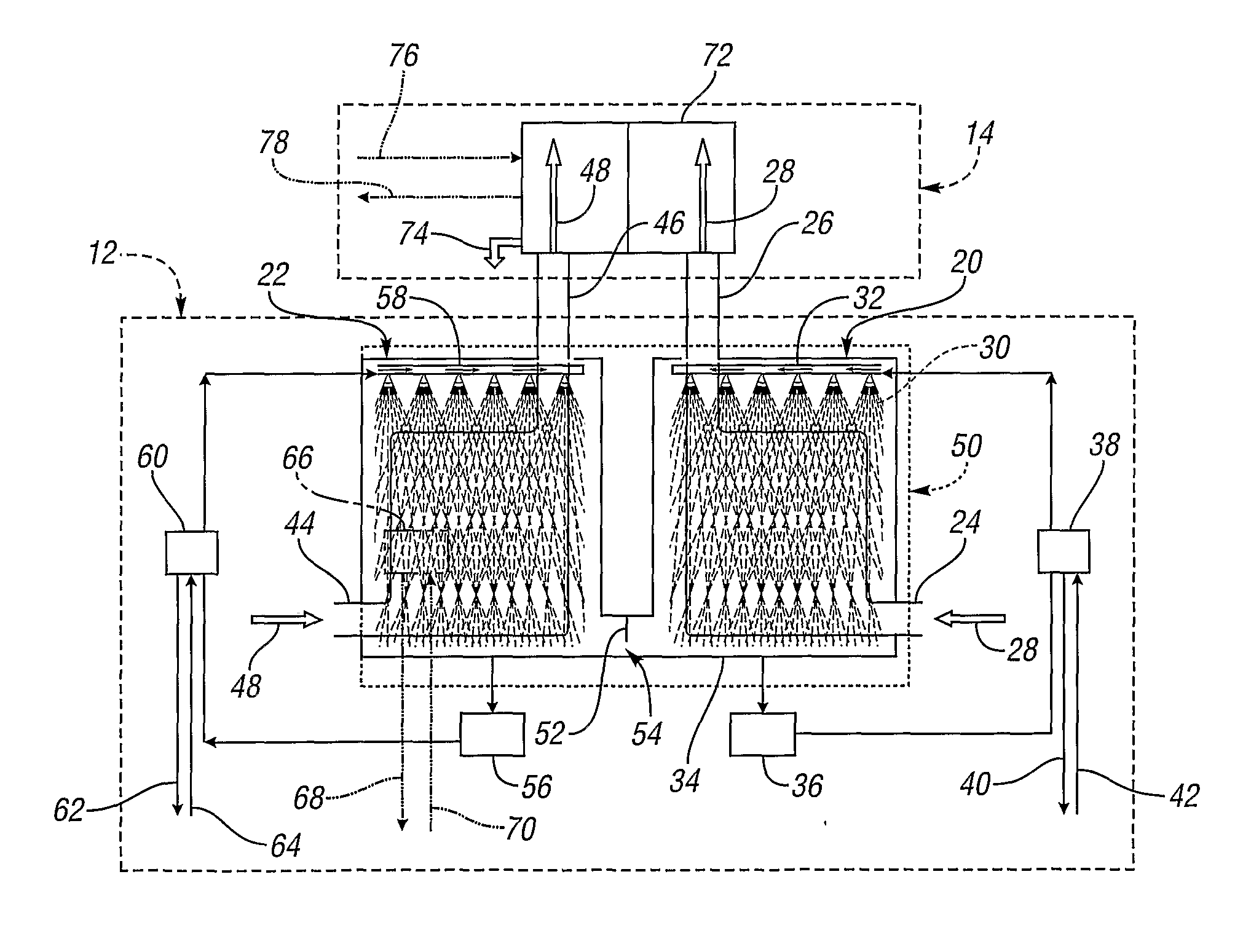
[0011]The invention further provides a method for producing water using a system including first and second chambers and a heat exchanger. The method includes passing a first airflow through the first chamber. At least some of the first airflow is exposed to a desiccant in the first chamber. This removes water from the first airflow and increases water content of the desiccant. At least some of the desiccant having increased water content is introduced into the second chamber. A second airflow is passed through the second chamber to facilitate evaporation of water from the desiccant into the second airflow. The second airflow is passed through the heat exchanger after its water content is increased. This facilitates cooling of second airflow and condensation of the water therefrom.
[0012]The invention also provides a system for producing water that includes a first chamber having an inlet and an outlet for facilitating movement of a first airflow into and out of the first chamber. The system also includes a desiccant capable of being introduced into the first chamber for removing water from the first airflow moving through the first chamber. A second chamber is configured to receive at least a portion of the desiccant after it removes water from the first airflow. The second chamber includes an inlet and an outlet for facilitating movement of a second airflow into and out of the second chamber. This facilitates evaporation of water from the desiccant in the second chamber into the second airflow. A system heat exchanger is configured to receive the second airflow from the second chamber and to facilitate cooling of the second airflow to extract water therefrom.
[0014]The present invention also provides a system and method for passing ambient air into a first chamber having a suitable desiccant material therein. The desiccant absorbs or adsorbs moisture from the air that comes in contact with the desiccant. In one embodiment, the air contacts desiccant by pumping air through a contact surface, such as a sponge, media, cooling coil, or cooling tower, that has desiccant dispersed therein. The desiccant and / or first chamber may be cooled to enable the more efficient transfer of water from the air to the desiccant. The desiccant absorbs or adsorbs water from the air, thereby transferring latent heat from the air as the water undergoes a phase change and condenses out of the air. Because the desiccant and / or first chamber are cooled, sensible cooling—i.e., cooling that is not based on a change of state—is also provided to the air. The resulting dry, cooled air is drawn out from the first chamber.
[0015]The now hydrous desiccant collects at the bottom of the first chamber and gets transferred to a second chamber. The second chamber transfer occurs either through active pumping or diffusion via a valve opening provided in a partition between the first and the second chambers. The valve opening enables equalization of desiccant levels in the first and the second chamber. The net flow of hydrous desiccant occurs from the first chamber to the second chamber until the level of the desiccant equalizes in the two chambers. The diffused or pumped hydrous desiccant in the second chamber can be heated and then again exposed to air. In one embodiment, the desiccant is sprayed into the interior of the second chamber. A heat exchanger such as a heating element warms the spray of hydrous desiccant falling from the nozzles, thereby evaporating moisture absorbed or adsorbed into the desiccant, generating hot humid air, and also regenerating substantially anhydrous desiccant.

Problems solved by technology

As a result it has been found that the water dispensing capability of prior art air-to-water generating systems is severely impaired in regions and seasons of low humidity.
This is too high a humidity level for climate controlled buildings, thereby rendering the machines less useful for most commercial and residential purposes and in certain portions of the world where the humidity level is low.

Method used


Image

  • System And Method For Producing Water
  • System And Method For Producing Water
  • System And Method For Producing Water

Examples


Embodiment Construction

)

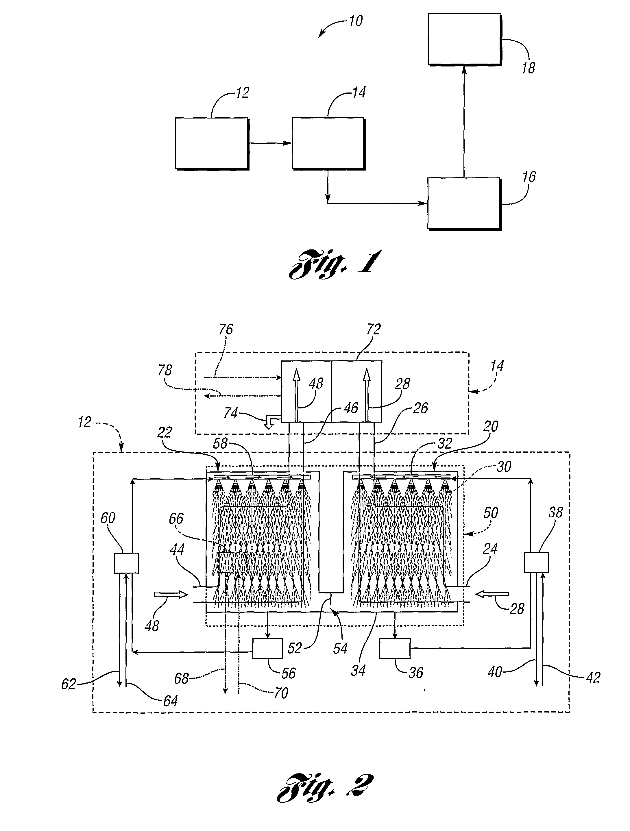
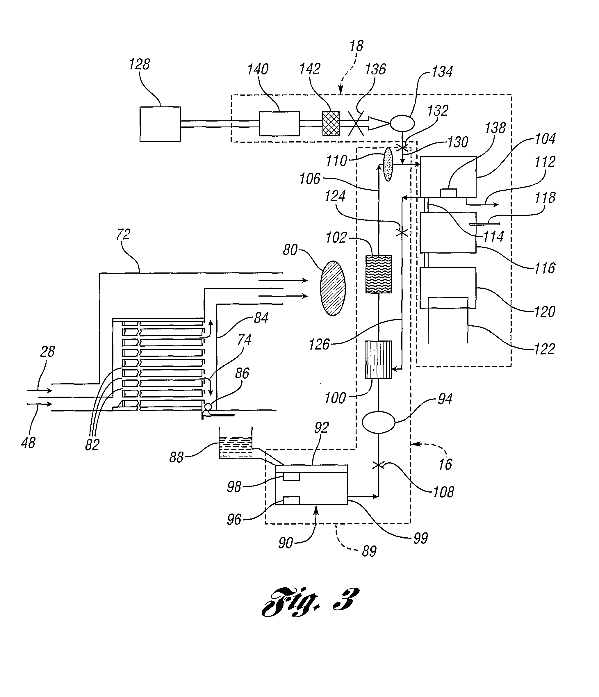
[0024]FIG. 1 shows a simplified schematic diagram of a water producing system 10 in accordance with one embodiment of the present invention. The system 10 includes a humid air manufacturing stage 12, a water extraction stage 14, a water purification and filtration stage 16, and a water dispensing stage 18. As described in more detail below, the humid air manufacturing stage 12 includes processes for removing moisture from an ambient air mass, and transferring it into another air mass by use of a desiccant material. The moisture collected in the desiccant material is evaporated into the second air mass, which results in the generation of warmer air with higher humidity than the initial ambient air.

[0025]The water extraction stage 14 includes a heat exchanger or absorber that cools the humid air stream manufactured in stage 12. The air stream is cooled to its dew point, thereby resulting in condensation of water vapor and production of liquid water. The condensed liquid water may be ...


PUM

PropertyMeasurementUnit
Temperatureaaaaaaaaaa
Timeaaaaaaaaaa
Water contentaaaaaaaaaa

Abstract

A method for producing water includes removing water from a first airflow using a first process which includes exposing at least some of the first airflow to a desiccant. This increases water content of at least some of the desiccant. At least some of the desiccant having increased water content is introduced into a second airflow. This facilitates evaporation of water from the desiccant into the second airflow, and increases water content of the second airflow. Water is then removed from the second airflow.

Description

CROSS-REFERENCE TO RELATED APPLICATIONS[0001]This application claims the benefit of U.S. provisional application Ser. No. 60 / 606,326 filed Aug. 31, 2004; U.S. provisional application Ser. No. 60 / 619,264 filed Oct. 15, 2004; and U.S. provision application Ser. No. 60 / 642,597, filed Jan. 10, 2005, each of which is hereby incorporated herein by reference.BACKGROUND OF THE INVENTION[0002]1. Field of the Invention[0003]The present invention relates to a system and method for producing water.[0004]2. Background Art[0005]Conventionally, water is collected from air using condensation systems. An exemplary condensation system provides a surface cooled to a temperature that is at or below the dew point of incoming air. As is well known in the art, the cooling of air at or below its dew point causes the condensation of water vapor from the air and a decrease in the absolute humidity of the air. The humidity of a volume of air is substantially determinative of the amount of water that can be in...

Claims


Application Information

Patent Timeline
IPC IPC(8): E03B3/28B01D53/14C02F1/32
CPCB01D53/261E03B3/28B01D53/263Y02A20/00C02F1/283C02F1/32C02F1/68C02F1/74C02F9/00B01D53/26
Inventor SHER, ABRAHAM M.
Owner AQUA SCI INC
Learn More