Integrated low noise amplifier and balun for MRI receivers

a low noise amplifier and receiver technology, applied in low noise amplifiers, using reradiation, instruments, etc., can solve the problems of reducing the diameter of the coil elements, reducing the quality and quantity of the signals captured by the receiver, and reducing the transmission of magnetic fields

Active Publication Date: 2008-06-12
GENERAL ELECTRIC CO
View PDF5 Cites 8 Cited by
  • Summary
  • Abstract
  • Description
  • Claims
  • Application Information

AI Technical Summary

Benefits of technology

[0007]The present invention is directed to an apparatus and method for integrating receiver electronics in a magnetic resonance imaging (MRI) system into a single device to overcome the aforementioned drawbacks. An integrated balun-LNA system is constructed to be enclosed within a standard balun to minimize volume and impact on the signals acquired by the RF receiver coils. Such a system would integrate electronic and passive components and use advanced electronic packaging technologies to achieve this minimization, thereby reducing the impact of the receiver electronics on image quality.
[0009]In accordance with another aspect of the present invention, an integrated balun-low noise amplifier (LNA) module includes a balun enclosure, a preamplifier partially located in a first chamber of the balun housing, and a common-mode inductor located in a second chamber of the balun housing, the second chamber also including a remaining portion of the preamplifier. Integrated balun-low noise amplifier (LNA) module also includes an internal shield separating the first chamber and the second chamber to reduce transmission of magnetic fields between the first and second chambers.

Problems solved by technology

Such a design can be problematic in that the baluns use large circuit components, that when located in, on, or near the receiver, can interfere with the magnetic flux field and thus reduce the quality and quantity of signals captured by the receiver.
Similar to the balun, the size of the preamplifier can also interfere with the magnetic flux field and reduce the quality and quantity of signals captured by the receiver.
This can be especially problematic as the quantity of receiver coil elements in a phased array increases and the diameter of the coil elements decreases.
This increased density of electronic components located near the receiver coil elements effects a higher likelihood of there being an adverse impact on image quality due to the higher relative disturbance of the magnetic flux field.

Method used


Image

  • Integrated low noise amplifier and balun for MRI receivers
  • Integrated low noise amplifier and balun for MRI receivers
  • Integrated low noise amplifier and balun for MRI receivers

Examples


Embodiment Construction

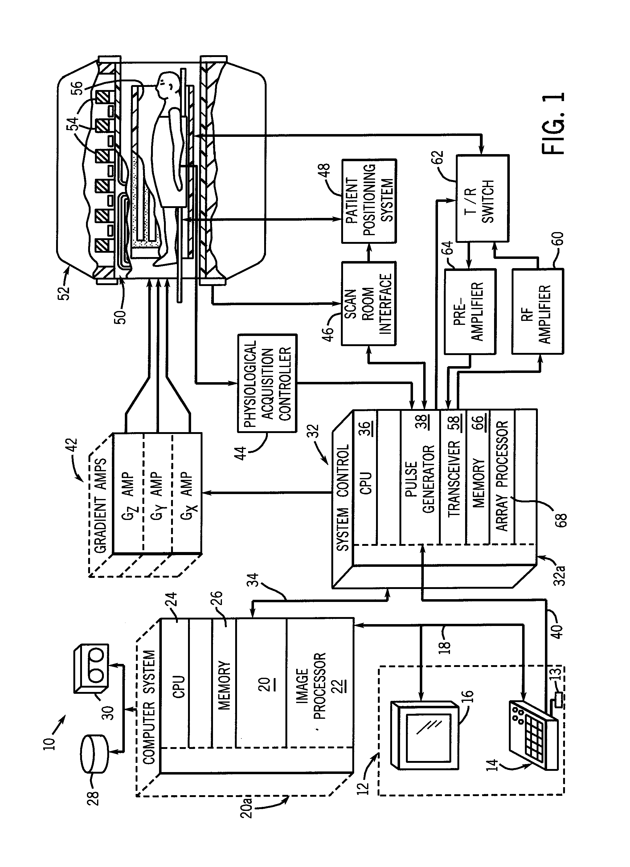
[0024]Referring to FIG. 1, the major components of a magnetic resonance imaging (MRI) system 10 incorporating the present invention are shown. This system is merely exemplary and one skilled in the art will readily understand that variations are not only possible, but frequently occur between various embodiments. For example, while some components are shown as a separate component, it may very well be incorporated into another component.

[0025]As shown in FIG. 1, the operation of MRI system 10 is controlled from an operator console 12 which includes a keyboard or other input device 13, a control panel 14, and a display screen 16. The console 12 communicates through a link 18 with a separate computer system 20 that enables an operator to control the production and display of images on the display screen 16. The computer system 20 includes a number of modules which communicate with each other through a backplane 20a. These include an image processor module 22, a CPU module 24 and a mem...


PUM


Abstract

An integrated balun-low noise amplifier (LNA) system is included in a magnetic resonance imaging system. The integrated balun-LNA system conditions electromagnetic signals received from at least one RF receiver coil. The integrated balun-LNA system is configured to be enclosed in a balun housing. The size of the integrated balun-LNA system minimizes component area and volume thereof on or near the RF receiver coil and thus, minimizes interference with the magnetic flux field.

Description

BACKGROUND OF THE INVENTION[0001]The present invention relates generally to receiver electronics in a magnetic resonance imaging (MRI) system, and, more specifically, to an integrated balun-low noise amplifier (LNA) system.[0002]MRI uses radio frequency pulses and magnetic field gradients applied to a subject in a strong homogenous magnetic field to produce viewable images. When a substance such as human tissue is subjected to a uniform magnetic field (polarizing field B0), the individual magnetic moments of the spins in the tissue attempt to align with this polarizing field, but precess about it, in random order, at their characteristic Larmor frequency. If the substance, or tissue, is subjected to a magnetic field (excitation field B1) which is in the x-y plane and which is near the Larmor frequency, the net aligned moment, or “longitudinal magnetization”, MZ, may be rotated, or “tipped”, into the x-y plane to produce a net transverse magnetic moment Mt. A signal is emitted by the...

Claims


Application Information

Patent Timeline
Patent Type & Authority Applications(United States)
IPC IPC(8): G01R33/36
CPCG01R33/3621G01R33/3685H03F2200/294H03F3/195G01R33/422
Inventor DE ROOIJ, MICHAEL A.GIAQUINTO, RANDY OTTO JOHNBURDICK, WILLIAM E.DELGADO, ELADIO CLEMENTE
Owner GENERAL ELECTRIC CO
Why Eureka
Try Eureka