
Distributed Architecture for IP-Based Telemetry Services

Active Publication Date: 2008-06-12
U S CELLULAR
View PDF4 Cites 25 Cited by
  • Summary
  • Abstract
  • Description
  • Claims
  • Application Information

AI Technical Summary

Benefits of technology

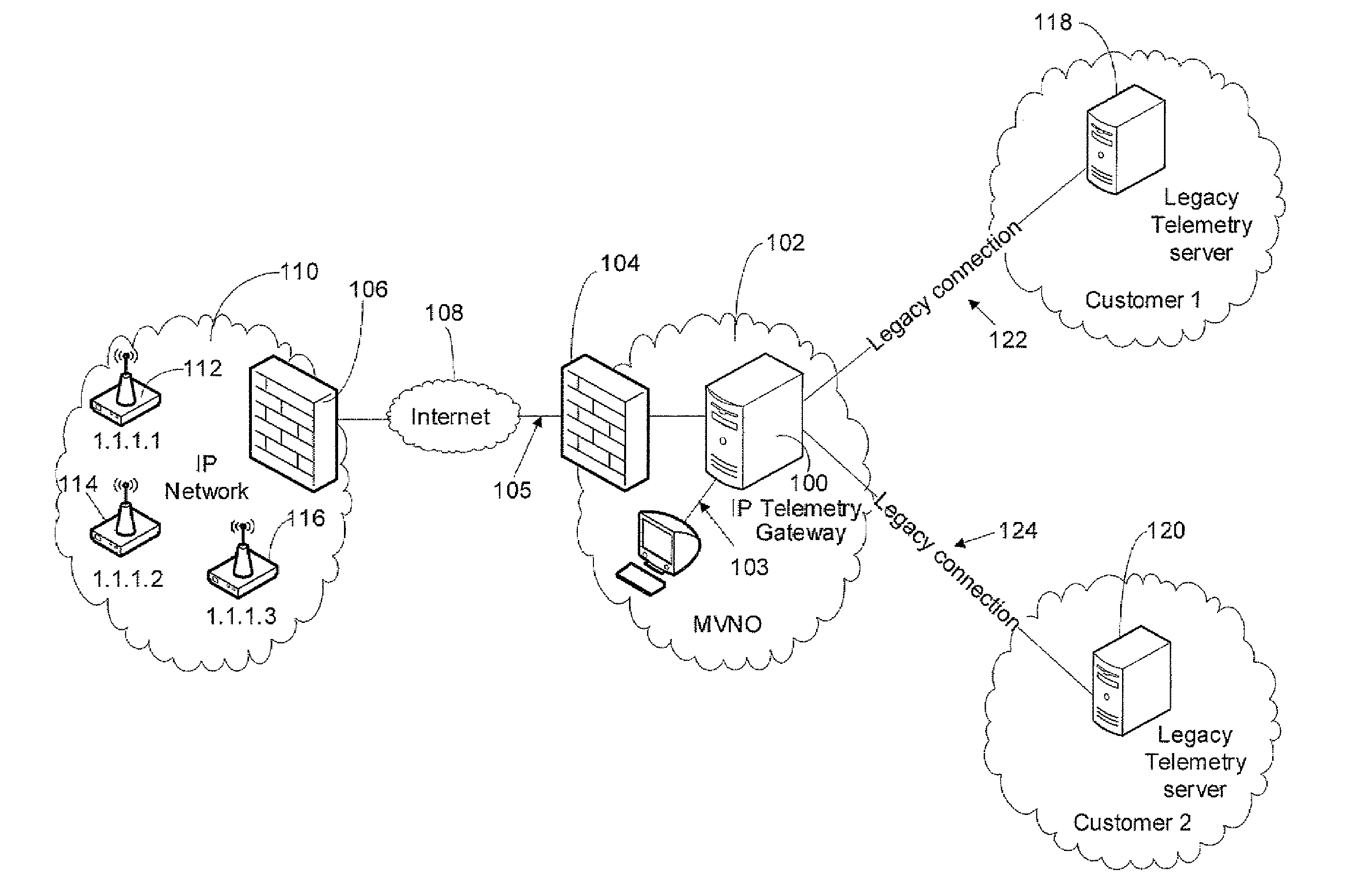
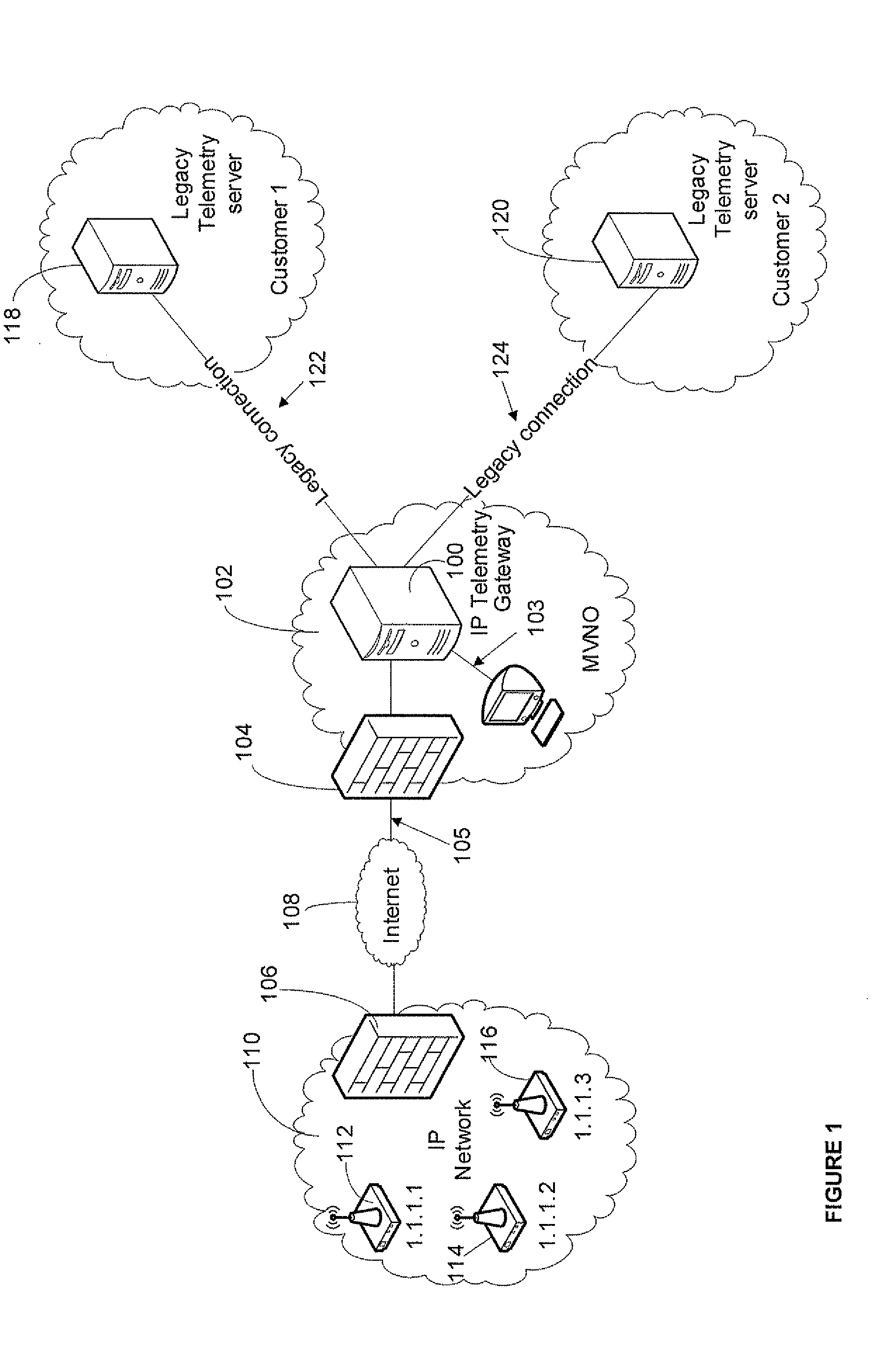
[0004]Embodiments of the invention are used to provide an IP telemetry system comprising an IP telemetry gateway managed and hosted by a mobile virtual network operator (MVNO) in order to relay the telemetry information between remote telemetry devices located in an IP network and one or more telemetry servers operated by legacy telemetry customers. The IP telemetry gateway is capable of communicating with the IP network and the legacy telemetry servers based on their respective native modes of communication. The IP telemetry gateway correlates an IP address assigned to each of the devices with another unique device identifier and communicates the telemetry information to one or more legacy telemetry servers via a legacy connection. This architecture allows the legacy telemetry customers to avoid the security and expense issues associated with updating the telemetry server equipment and software, while taking full advantage of expanded capabilities of IP based telemetry. Additionally, this allows the operator of the IP network to shift the additional resources needed for maintaining and managing the IP telemetry gateway and legacy connections to the MVNO.

Problems solved by technology

Although a conversion to IP based telemetry services is often desirable, many legacy telemetry customers do not wish to host new telemetry server equipment and software due to associated expense and security implications.
Similarly, although the wireless network operators often desire to incorporate legacy telemetry customers into their current IP based telemetry services, doing so may require additional expense and resources for managing the legacy connections.

Method used


Image

  • Distributed Architecture for IP-Based Telemetry Services
  • Distributed Architecture for IP-Based Telemetry Services
  • Distributed Architecture for IP-Based Telemetry Services

Examples


Embodiment Construction

[0014]The following examples further illustrate the invention but, of course, should not be construed as in any way limiting its scope.

[0015]Turning to FIG. 1, an implementation of a system contemplated by an embodiment of the invention is shown with reference to the Internet Protocol (IP) telemetry system environment. To distribute the telemetry system resources, an IP telemetry gateway 100 resides in a third party network 102, which is preferably operated by a mobile virtual network operator (MVNO). In this embodiment, an MVNO network 102 manages and hosts the IP telemetry gateway 100 to relay telemetry information between an IP network 110 and one or more telemetry servers 118, 120 based on modes of communication native to the network 110 and telemetry servers 118, 120, respectively. The MVNO network 102 includes a management connection 103, implemented via software or hardware, to the IP telemetry gateway 100 to maintain the operational aspects of the gateway 100 and associated ...


PUM


Abstract

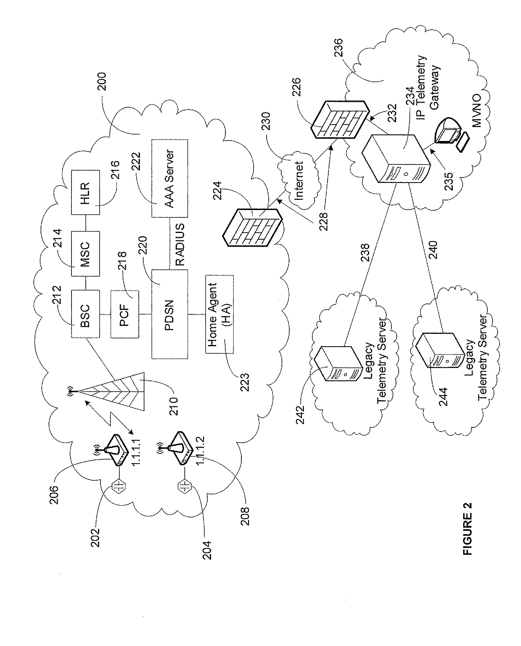
A system and method are described whereby an IP telemetry gateway is hosted by an MVNO in order to relay the telemetry information between remote devices located in an IP network and telemetry servers operated by legacy telemetry customers. In an embodiment, the IP network is a CDMA2000 1× wireless network. Once the IP network identifies a device as part of the telemetry network, it assigns such device a static private IP address. A VPN connection is used to extend the private network of remote devices to the IP telemetry gateway. The IP telemetry gateway maps each remote device's legacy address to its corresponding IP address in order to communicate with the legacy servers and the wireless network via circuit switched and packet data connections respectively. Preferably, the remote devices maintain an always on data connection to allow the telemetry servers to address the remote devices at any time.

Description

FIELD OF THE INVENTION[0001]This invention relates generally to the field of machine-to-machine communication and more specifically to the field of Internet Protocol based telemetry services.BACKGROUND OF THE INVENTION[0002]Telemetry services allow remote measurement and reporting of information for subsequent storage or processing. Telemetry applications are used in a wide variety of industries, including public utilities, security, health care, law enforcement, and government sectors. Transmission of telemetry data involves a machine-to-machine communication between a client device and a home server. Typical examples of telemetry applications include remote reading of utility and parking meters, audio / video security surveillance, alarm monitoring, and remote sensor monitoring. Legacy telemetry solutions are based on a circuit switched model, in which a telemetry server periodically communicates with individual client devices by dialing each device's number via an analog communicat...

Claims


Application Information

Patent Timeline
IPC IPC(8): H04M11/00
CPCH04L12/66H04L29/12584H04L61/6054H04L61/2596H04L29/12905H04L2101/654H04L41/344
Inventor ABICHANDANI, JAIDEEPIRIZARRY, MICHAELSAXENA, NAROTHUM
Owner U S CELLULAR
Learn More