Method and system for low speed control of a video surveillance system motor

Active Publication Date: 2008-06-12
JOHNSON CONTROLS TYCO IP HLDG LLP
View PDF5 Cites 5 Cited by
  • Summary
  • Abstract
  • Description
  • Claims
  • Application Information

AI Technical Summary

Benefits of technology

[0015]In accordance with one aspect, the present invention advantageously provides a motor control system in which a first encoder outputs a plurality of signals having corresponding signal edges. The plurality of signals includes a first edge and a second edge and are based on the speed of a

Problems solved by technology
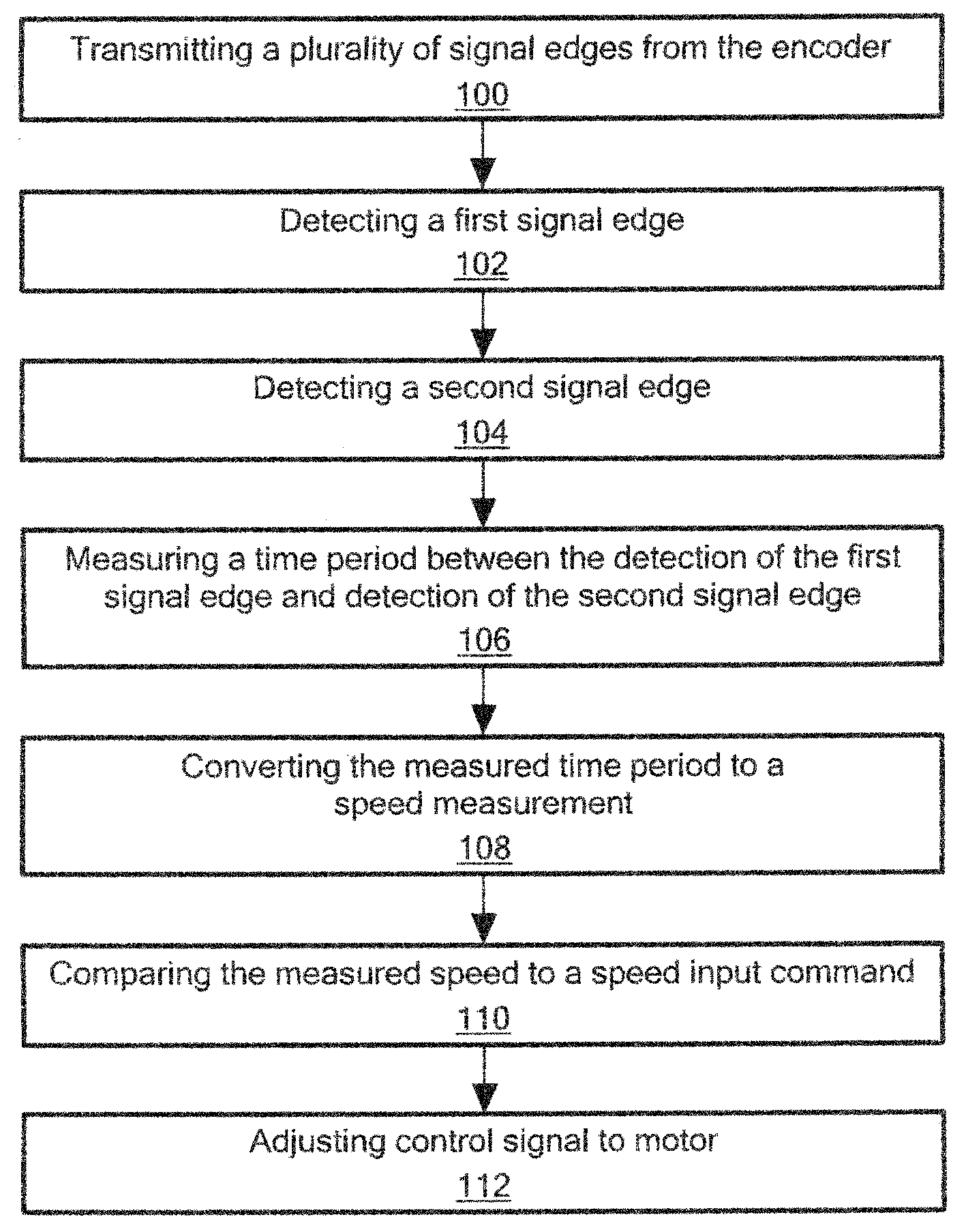
However, increasing the gear ratio reduces the maximum speed that can be achieved with the same RPM motor.
Installing a larger, higher speed, higher torque motor could improve high speed control while allowing a larger gear ratio, but the drive system would be larger and more costly.
It is difficult to achieve smooth control of a video camera platform below 1.0° per second when using a limited gearbox ratio, a limited motor size to reduce physical area and cost, and an encoder with a practical number of pulses per revolution.
At very low speeds, there are so few pulses per second that the speed reading acquired in a 10 ms period is not very accurate.
A second problem at very low speed

Method used


Image

  • Method and system for low speed control of a video surveillance system motor
  • Method and system for low speed control of a video surveillance system motor
  • Method and system for low speed control of a video surveillance system motor

Examples


Embodiment Construction

[0028]The present invention provides a system and method for driving a video surveillance system. Referring now to the drawing figures in which like reference designators refer to like elements, there is shown in FIG. 3, a video surveillance system constructed in accordance with the principles of the present invention and designated generally as “50”. The video surveillance system 50 may generally include a housing assembly 52 in operative communication with a camera assembly 54, each of which may contain various mechanical and electrical components facilitating the operation thereof.

[0029]Now referring to FIG. 4, in particular, the housing assembly 52 may include one or more housing elements 55a, 55b, 55c (referred to collectively herein as housing elements 55) encasing or otherwise enclosing a portion of the housing assembly contents. The housing elements 55 may be movably engaged to one another by a rotatable bearing pan platform 56 or similar mechanical coupling. The housing ass...


PUM


Abstract

The present invention provides a method and system that improve the low-speed control stability of a video camera assembly, including a video camera, a tilt motor operable to tilt the video camera and a pan motor operable to pan the video camera. A first encoder is coupled to one of the tilt motor and pan motor. The first encoder outputs a plurality of signals having corresponding signal edges, based on a rotation speed of the one of the tilt motor and pan motor. A first controller is in electrical communication with the first encoder. The first controller determines a speed of the one of the tilt motor and pan motor at least in part by correlating a time period between detection of the first edge and detection of the second edge to the speed of the at least one tilt motor and pan motor.

Description

CROSS-REFERENCE TO RELATED APPLICATION[0001]This application is related to and claims priority to U.S. Provisional Patent Application Ser. No. 60 / 873,379, filed Dec. 7, 2006, entitled Video Dome and System, the entirety of which is incorporated herein by reference.STATEMENT REGARDING FEDERALLY SPONSORED RESEARCH OR DEVELOPMENT[0002]n / aFIELD OF THE INVENTION[0003]The present invention relates to a video camera control system, and in particular, a system for controlling the movement of a video dome and a method of use thereof.BACKGROUND OF THE INVENTION[0004]Video camera lens systems continue to evolve, such that they have higher and higher zoom factors. When using the higher zoom factors it is desirable to control the pan and tilt speeds of video dome systems at an inversely-proportional rate, i.e., slower speeds in order to follow distant objects. Methods to control motor speed with a combination of proportional, integral and derivative terms (“PID”) for video surveillance systems a...

Claims


Application Information

Patent Timeline
IPC IPC(8): H02P7/29
CPCG05B19/4062G05B2219/42288H02H7/0856G08B13/1963H04N23/695
Inventor BERKEY, THOMAS F.DEJESUS, CARLOS
Owner JOHNSON CONTROLS TYCO IP HLDG LLP
Why Eureka
Try Eureka