
Catalyst And System For Reducing Exhaust Of Diesel Engines

Inactive Publication Date: 2008-06-19
END SOLUTIONS
View PDF5 Cites 16 Cited by
  • Summary
  • Abstract
  • Description
  • Claims
  • Application Information

AI Technical Summary

Benefits of technology

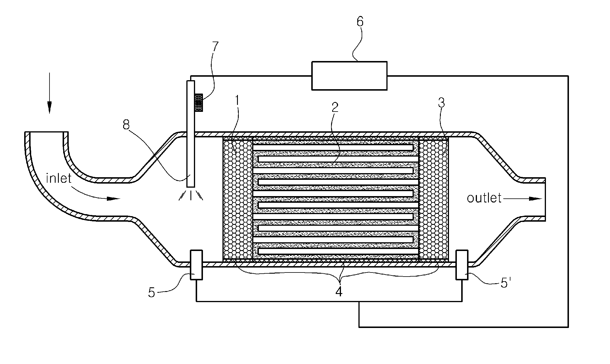
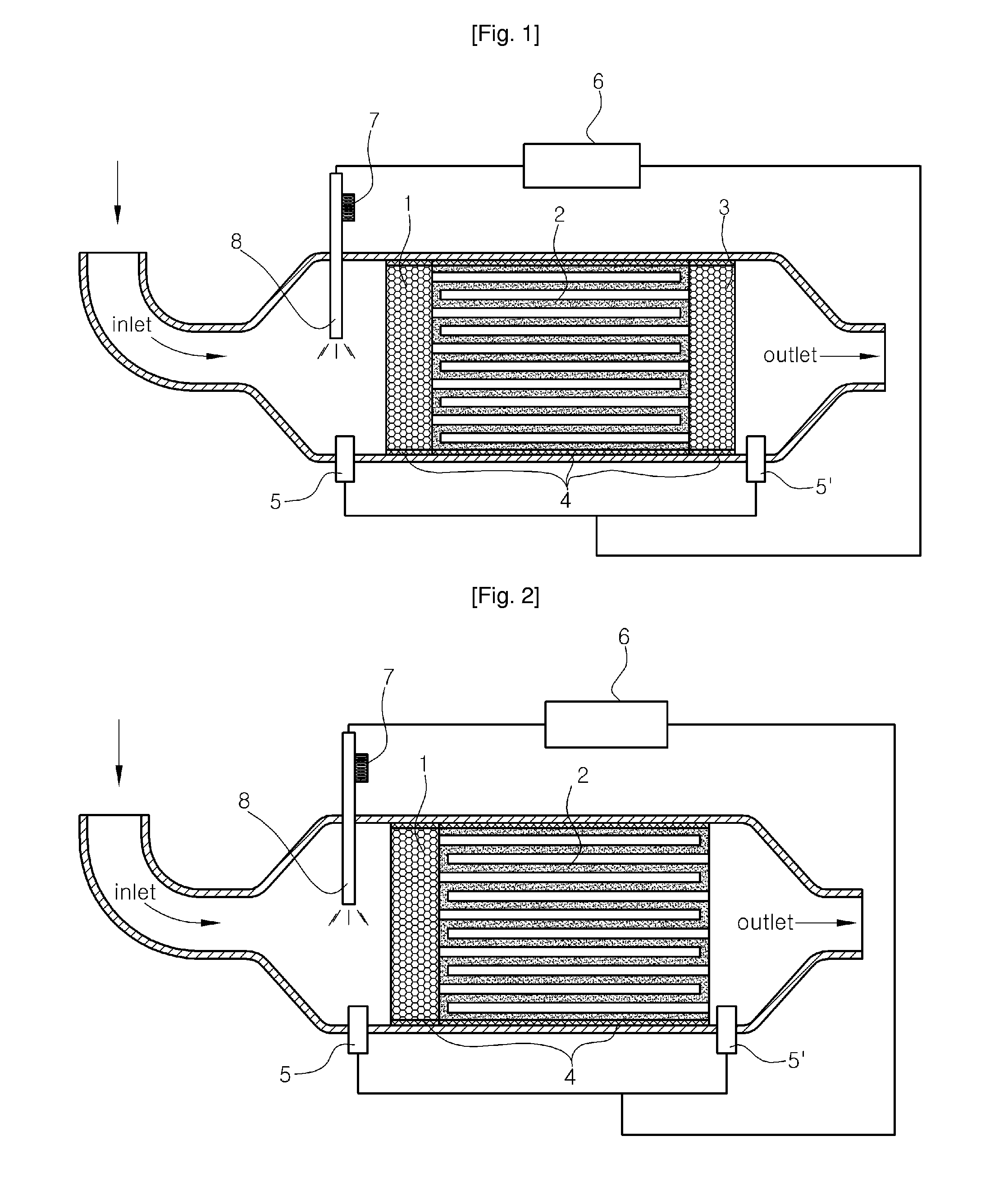
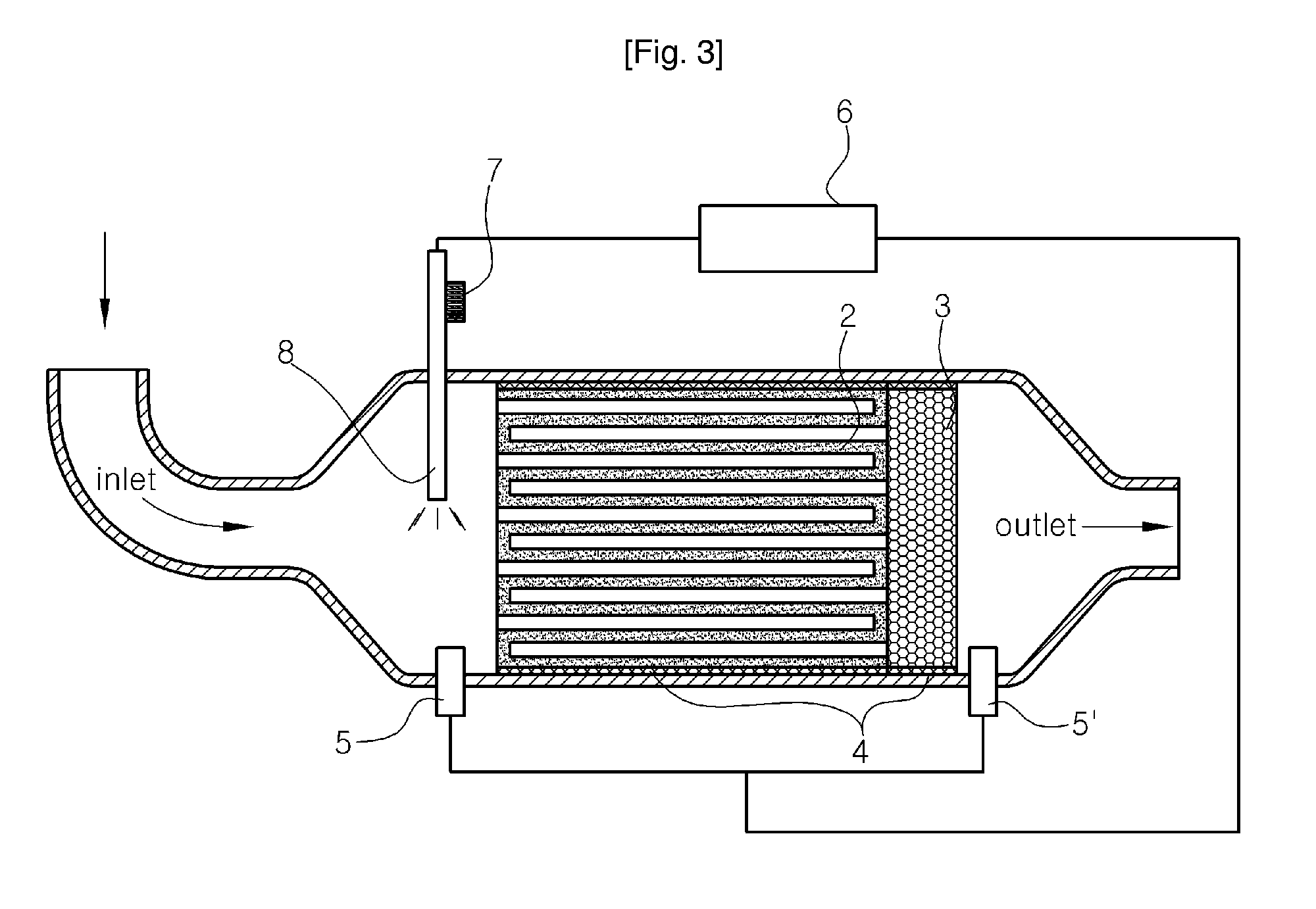
[0034]In the diesel exhaust after-treatment system, the catalyzed ceramic filter has a low balance point temperature, and thus, it can be operated even at low temperatures without an increase in back pressure. At a lower temperature, it can be continuously regenerated by the injection of heated light oil without applying excessive load to engines. Also, it can effectively remove carbon

Problems solved by technology

However, the prior catalysts disclosed in said patents have a problem in that they decompose volatile organic compounds and carbon monoxide at a space velocity of 30,000 h1-50,000 h1, indicating a too-low treatment rate per unit of time.
However, the method has problems in that it requires a large amount of catalysts corresponding to a space velocity of about 3,000 h1-10,000 h1, and needs to use an additional system for supplying urea or ammonia, leading to an increase in cost.
Another problem is that, when a portion of ammonia is discharged as exhaust, it can cause environmental problems.
However, these catalysts are disadvantageous in that they have a lower conversion rate than the selective catalytic reduction, and low resistance to water, a

Method used


Image

  • Catalyst And System For Reducing Exhaust Of Diesel Engines
  • Catalyst And System For Reducing Exhaust Of Diesel Engines
  • Catalyst And System For Reducing Exhaust Of Diesel Engines

Examples


Example

EXAMPLE 1

DPF

[0060]500 g of gamma-alumina and 500 g of BaTiO2 were wet pulverized with a ball mill for 20 hours to prepare an aqueous slurry. Then, a ceramic filter, which was 11.25 inches in inner diameter and 14 inches in length and had about 200 pore cells per square inch, was immersed in the slurry and drawn out from the slurry, and an excess of slurry in the cells was blown off with compressed air. The resulting ceramic filter was dried at 120° C. for 12 hours. The dried ceramic filter was impregnated by immersion in an aqueous chloroplatinic acid solution containing 20 g of Pt as the platinum-group metal component (A) and 5 g of Rb as the fifth-period metal component (B), and then dried at 120° C. for 12 hours. The dried ceramic filter was calcined at 400° C. for 2 hours, thus manufacturing a catalyzed ceramic filter for DPF.

Example

EXAMPLE 2

DPF

[0061]The process of Example 1 was repeated except that the component (A) was 15 g of Pt and the component (B) was 5 g of Sr.

Example

EXAMPLE 3

DPF

[0062]The process of Example 1 was repeated except that the component (A) was 15 g of Pd and the component (B) was 5 g of Y.


PUM

PropertyMeasurementUnit
Fractionaaaaaaaaaa
Fractionaaaaaaaaaa
Percent by massaaaaaaaaaa

Abstract

The present invention relates to a novel catalyst composition for use in a nitrogen oxide removal unit (DeNOx), a diesel particulate filter (DPF) and a diesel oxidation catalyst (DOC) unit, as well as a diesel exhaust after-treatment system comprising the same. In the diesel exhaust after-treatment system, the catalyzed ceramic filter ha s a low balance point temperature, and thus it can be operated even at low temperatures without an increase in back pressure. At a lower temperature, it can be continuously regenerated by the injection of heated light oil without applying excessive load to engines. Also, it can efficiently remove carbon monoxide and hydrocarbon with a high efficiency at low temperatures. In addition, according to the present invention, the number of particulate matters of less than 1 D can be decreased by the DOC catalyst honeycomb structure positioned in the rear of the ceramic filter, and nitrogen oxide can be removed by the DeNOx catalyst honeycomb structure positioned in front of the ceramic filter.

Description

TECHNICAL FIELD [0001]The present invention relates to a catalyst for reducing exhaust from diesel engines, and a diesel engine exhaust after-treatment system including the same.BACKGROUND ART [0002]Worldwide interest in the environment started to increase in the latter half of the 1980s, and particularly, solutions to air pollution started to be discussed worldwide starting with the Framework Convention on Climate Change. Thus, in the automobile field, studies on fuel economy and safety as well as the reduction of exhaust gas have also been recently actively conducted.[0003]Components of exhaust from diesel automobiles, which are currently regulated by the law, are carbon monoxide (CO), hydrocarbons (HC), nitrogen oxides (NOx) and particulate matters (PM). Diesel engines have low emissions of carbon monoxide and hydrocarbon because fuel is combusted at a high excess air ratio, whereas they have high emissions of nitrogen oxides and particulate matters. Thus, studies on the reductio...

Claims


Application Information

Patent Timeline
IPC IPC(8): F01N3/035B01J23/44B01J23/42B01J23/46B01J23/40B01J23/58B01J23/50B01J21/06
CPCB01D53/945F01N13/0097B01D2255/2042B01D2255/2092B01D2258/012B01J23/002B01J23/58B01J23/63B01J23/6484B01J37/0242B01J2523/00F01N3/0256F01N3/035F01N3/0821F01N3/208F01N9/002F01N2510/065F01N2560/08F01N2610/03F01N2610/10F01N2610/146F01N2900/08B01D2255/102Y02T10/24Y02T10/22Y02T10/47B01J2523/24B01J2523/25B01J2523/31B01J2523/47B01J2523/828B01J2523/14B01J2523/36B01J2523/824B01J2523/15B01J2523/56B01J2523/821B01J2523/11B01J2523/16B01J2523/33Y02T10/12Y02T10/40F21S8/00F21V17/10F21W2131/101
Inventor KIM, MIN-YONGLEE, HAE-SOOCHUNG, JAE-HOON
Owner END SOLUTIONS
Learn More