

Purge gas injection plate and manufacturing method thereof
- Summary
- Abstract
- Description
- Claims
- Application Information
AI Technical Summary
Benefits of technology
Problems solved by technology
Method used
Image

Examples
first embodiment
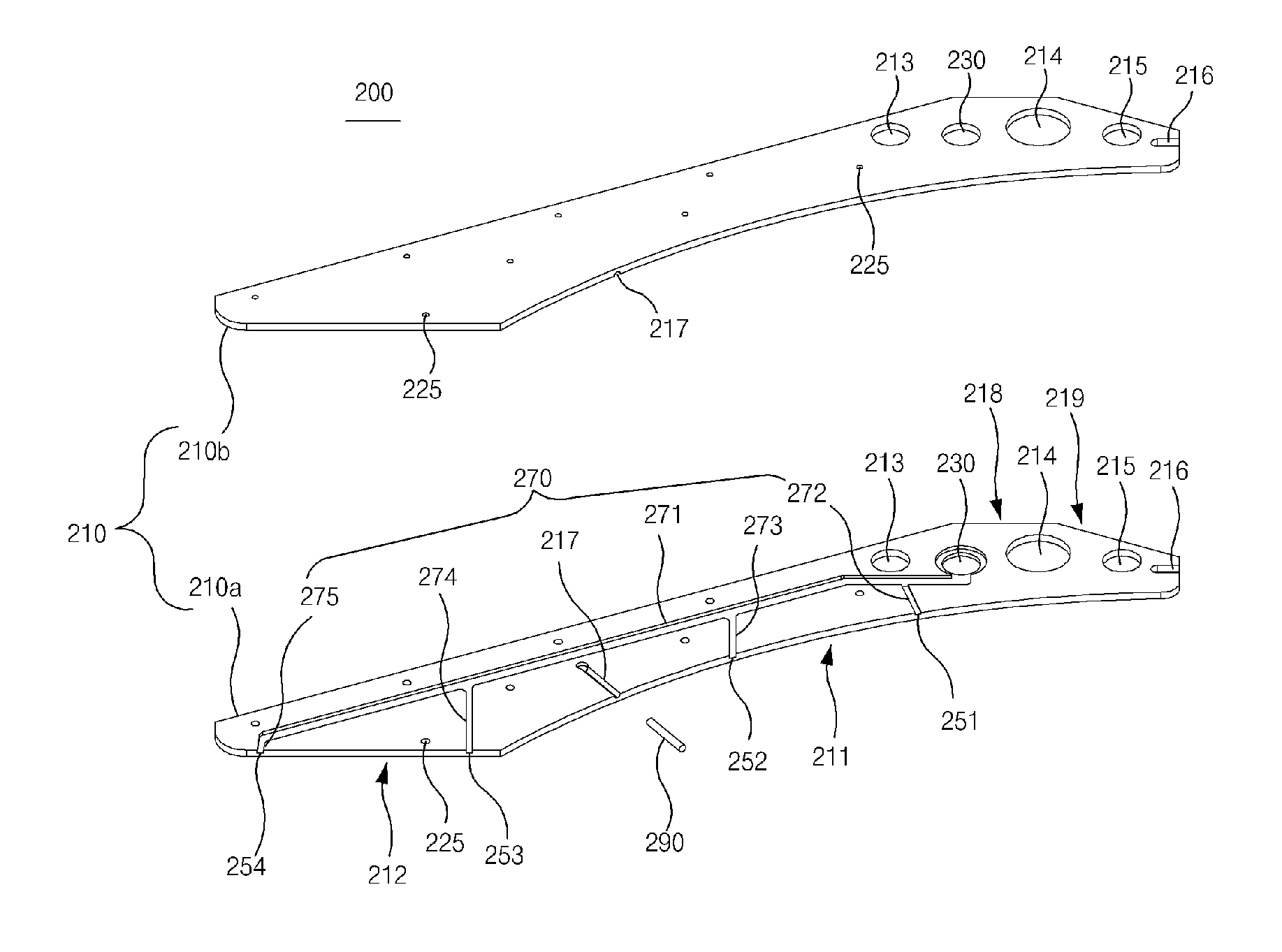
[0072]As illustrated in FIG. 3, a purge gas spraying plate 200 according to the present invention is configured to include a plate 210, an inlet 230 formed in the plate 210, and a flow path 270 in communication with the inlet 230.
[0073]The plate 210 may be formed by vertically coupling a first plate 210a and a second plate 210b.
[0074]The first plate 210a includes a concave portion 211 formed in a circular arc shape at one side facing a wafer, and a front portion 212 continuously formed from a front end portion of the concave portion 211 and having a width decreasing toward a front of the first plate 210a.
[0075]The other side of the first plate 210a includes a first inclined surface 218 having a slope around the inlet 230 in a direction of the concave portion 211 while linearly continuing from an front end portion of the front portion 212 to a rear end of the first plate 210a, and a second inclined surface 219 continuing from the first inclined surface 218, having a slope around a ...
second embodiment
[0173]The purge gas spraying plate 600 according to the present invention may have an appearance formed in a rectangular shape as illustrated in FIG. 10.
[0174]The purge gas spraying plate 600 includes a plate formed by coupling a first plate and a second plate, an inlet 630, and a flow path, the same as in the purge gas spraying plate 200 according the first embodiment of the present invention.
[0175]The plate has the rectangular shape, a support rod 690 inserted into one side of the plate, a flow path and first to third through holes 613 to 615 formed in a rear end of the plate, a coupling groove formed in a rear end portion, and a bolt hole (not shown) formed in a surface thereof.
[0176]The description of the functions and effects of the support rod 690, the inlet 630, the first to third through holes 613 to 615, the coupling groove, and the bolt hole will be omitted because it is the same as those of the purge gas spraying plate 200 according to the first embodiment of the present ...
third embodiment
[0182]As illustrated in FIG. 11, a purge gas spraying plate 600′ according to the present invention may further include first to fifth nozzles 682 to 686.
[0183]The first to fifth nozzles 682 to 686 are installed to respectively communicate with first to fifth branch flow paths 672′ to 676′, and spray a purge gas introduced from an inlet 630 to a wafer W.
[0184]In addition, the lengths of the first to fifth nozzles 682 to 686 are formed along a shape of a curvature of the wafer W facing one side of the purge gas spraying plate 600′.
[0185]That is, the lengths thereof become longer in order of the first nozzle 682 to the fifth nozzle 686 according to the shape of the wafer W, and thus, a virtual line which connects one end portions of the first to fifth nozzles 682 to 686 which spray a purge gas is formed to have a circular arc shape.
[0186]Thus, even when the one side of the purge gas spraying plate 600′ does not include a concave portion having a circular arc shape unlike the purge gas...
PUM
| Property | Measurement | Unit |
|---|---|---|
| Angle | aaaaa | aaaaa |
| Length | aaaaa | aaaaa |
| Shape | aaaaa | aaaaa |
Abstract
Description
Claims
Application Information