Hydraulic drive system

Active Publication Date: 2014-12-18
HITACHI CONSTR MASCH CO LTD
View PDF6 Cites 6 Cited by
  • Summary
  • Abstract
  • Description
  • Claims
  • Application Information

AI Technical Summary

Benefits of technology

[0011]The present invention makes it possible to provide a hydraulic drive system capable of effectively removing particulate matter that has built up in a filter and configured to preferentially cause a steering to ope

Problems solved by technology

For construction machinery equipped with an engine, there is a technical problem to solve, which is to reduce particulate matter (which may hereinafter be simply referred to a

Method used


Image

  • Hydraulic drive system
  • Hydraulic drive system
  • Hydraulic drive system

Examples


Example

Embodiment 1

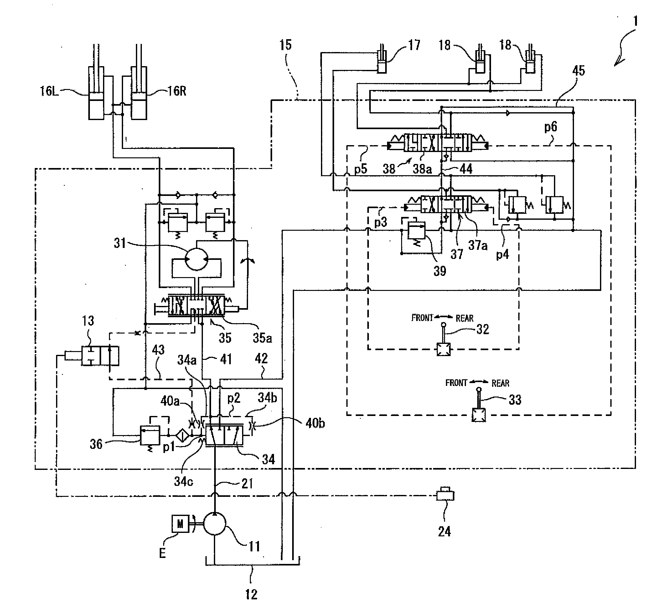
[0017]The hydraulic drive system 1 according to Embodiment 1 of the present invention is included in construction machinery, for example, a wheel loader. The wheel loader includes a loading / unloading apparatus, for example, a bucket and hoist. The wheel loader is configured to scoop up earth and sand, stones and rocks, and the like by operating the bucket, and lift the bucket by operating the hoist. The wheel loader with such a configuration is configured to bend its body and operate the bucket and hoist by means of the hydraulic drive system 1.

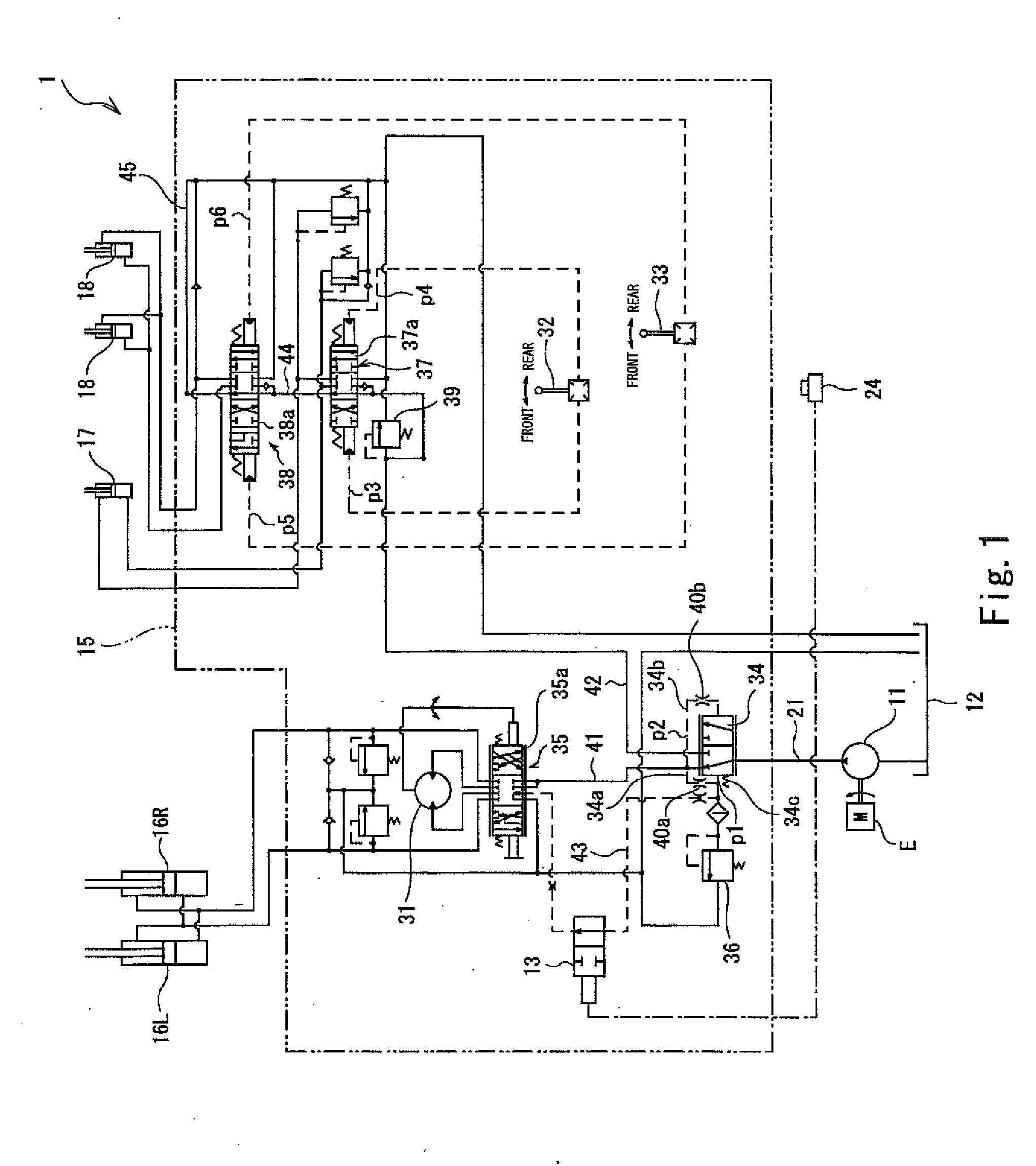
[0018]As shown in FIG. 1, fundamentally, the hydraulic drive system 1 includes a hydraulic pump 11, a tank 12, a drive device 15, steering actuators 16L and 16R, a bucket actuator 17, and two hoist actuators 18. The hydraulic pump 11 is a fixed displacement pump, and is connected to an output shaft of an engine E via a gear mechanism. When the engine E is driven and the output shaft is rotated, the hydraulic pump 11 takes in hydra...

Example

Embodiment 2

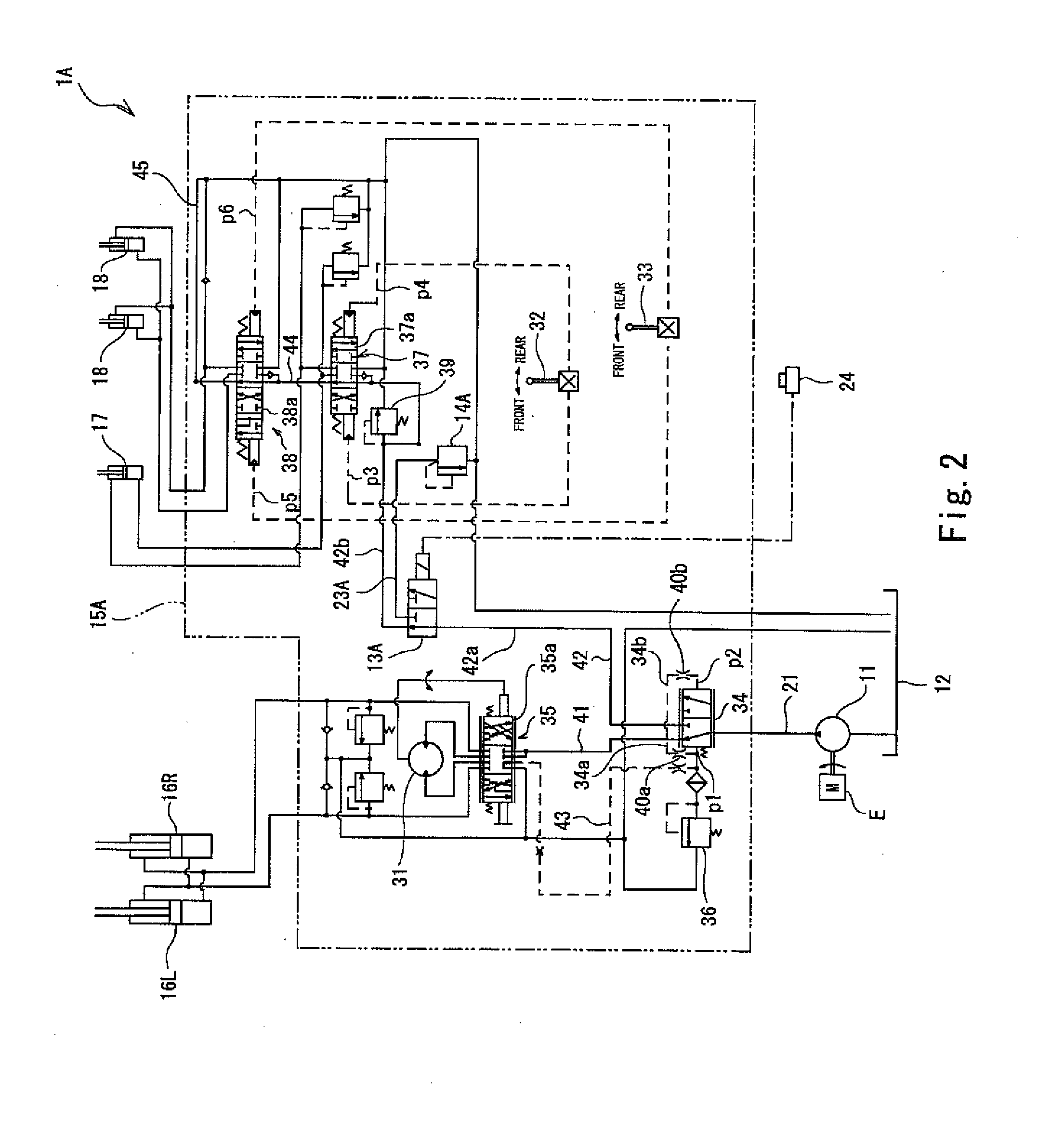
[0039]The configuration of the hydraulic drive system 1A according to Embodiment 2 of the present invention is similar to that of the hydraulic drive system 1 according to Embodiment 1. Therefore, the configuration of the hydraulic drive system 1A according to Embodiment 2 is described below with a focus on its differences from the configuration of the hydraulic drive system 1 according to Embodiment 1, and the description of the same configuration as that of the hydraulic drive system 1 according to Embodiment 1 is omitted. The same is true of the hydraulic drive system 1B according to Embodiment 3, which will be described below.

[0040]As shown in FIG. 2, in a drive device 15A of the hydraulic drive system 1A, a solenoid switching valve 13A is disposed in the loading / unloading apparatus-side main passage 42. The solenoid switching valve 13A, which serves as a direction switching valve, is also connected to a relief passage 23A. The solenoid switching valve 13A is configu...


PUM


Abstract

A hydraulic drive system includes a pump, a steering actuator, a loading/unloading apparatus actuator, a drive device, a relief valve, and an input unit. The drive device: flows hydraulic oil from the pump to the loading/unloading apparatus actuator when an operating tool is operated; flows the hydraulic oil from the pump to the steering actuator when a steering has become an operated state from a non-operated state regardless of an operation of the operating tool; and causes the hydraulic oil from the pump to be discharged to a tank via the relief valve to increase the torque of an engine when an increase instruction is inputted to the input unit and the steering is in a non-operated state.

Description

TECHNICAL FIELD[0001]The present invention relates to hydraulic drive systems capable of: flowing hydraulic oil from a pump to a steering actuator and a loading / unloading apparatus actuator, which are connected parallel to a pump, thereby causing these actuators to operate; and flowing the hydraulic oil to the steering actuator preferentially.BACKGROUND ART[0002]For construction machinery equipped with an engine, there is a technical problem to solve, which is to reduce particulate matter (which may hereinafter be simply referred to as PM) such as soot contained in exhaust gas discharged from the engine. In order solve the problem, the construction machinery includes, for example, filters in an exhaust gas pipe, a muffler, and the like. PM is collected by the filters, and then the exhaust gas is discharged to the atmosphere.[0003]However, if PM is kept collected, then the PM builds up inside the filters, thereby clogging the filters. In order to suppress such clogging, it is necessa...

Claims


Application Information

Patent Timeline
IPC IPC(8): F15B21/00F16H61/4017F15B1/26
CPCF15B21/001F16H61/4017F15B1/26E02F9/2228E02F9/2246F15B11/162F15B2211/4053F15B2211/428F15B2211/6355F15B2211/6658F15B2211/67B62D5/063E02F9/225E02F9/2285F01N3/023F01N2590/08F15B2211/20523F15B2211/252F15B2211/7135F15B2211/781F15B2211/85
Inventor TANAKA, SHINICHIROKODERA, HIROYASUITO, MAKOTO
Owner HITACHI CONSTR MASCH CO LTD
Why Eureka
Try Eureka