Discharge field emission device, and light source apparatus and display apparatus applying the same

a discharge field and emission device technology, applied in the direction of discharge tube/lamp details, discharge tube luminescence screens, discharge tube main electrodes, etc., can solve the problems of both aforementioned luminescence structures, high cost, and considerable energy loss, and achieve good luminescence efficiency and easy production

Inactive Publication Date: 2008-06-19
IND TECH RES INST
View PDF5 Cites 8 Cited by
  • Summary
  • Abstract
  • Description
  • Claims
  • Application Information

AI Technical Summary

Benefits of technology

[0009]The present invention relates to a discharge emission device that has good luminescence efficiency and is easy to be produced.
[0010]The present invention also relates to a light source apparatus using aforementioned discharge field emission device, configured to provide a good and uniform light source and has the advantages of low cost and good production yield.
[0011]The present invention also relates to a display apparatus using aforementioned discharge field emission devices as display pixels, configured to provide good display quality and reduce the cost and complexity of production.
[0015]As above described, in the present invention, thin conductive gas is used for inducing electrons from the cathode easily, so the problems that may occur when fabricating electron emitter on the cathode can be avoided. In addition, since the conductive gas used is thin, so the mean free path of electrons is wide, a lot of electrons react with the phosphor to emit light before they collide with gas. In other words, the discharge field emission device of present invention has high luminescence efficiency and good production yield, and is easy to be produced.

Problems solved by technology

However, there are disadvantages in both aforementioned luminescence structures.
Moreover, the luminescence mechanism of gas discharge requires two processes to emit a visible light, thus, the energy loss is considerable, and it will cost more if plasma needs to be generated during the process.
In another aspect, electron emitter has to be evenly grown or disposed on the cathode of the field emission light source, however, the technology of mass-producing of such cathode structure is still immature, and the problems of poor electron emitter uniformity and poor production yield are still not resolved.
Moreover, the space between the cathode and the anode of field emission light source requires precise control, and ultra high vacuum packaging is difficult to process, so the cost of production increases accordingly.

Method used


Image

  • Discharge field emission device, and light source apparatus and display apparatus applying the same
  • Discharge field emission device, and light source apparatus and display apparatus applying the same
  • Discharge field emission device, and light source apparatus and display apparatus applying the same

Examples


Embodiment Construction

[0025]Reference will now be made in detail to the present preferred embodiments of the invention, examples of which are illustrated in the accompanying drawings. Wherever possible, the same reference numbers are used in the drawings and the description to refer to the same or like parts.

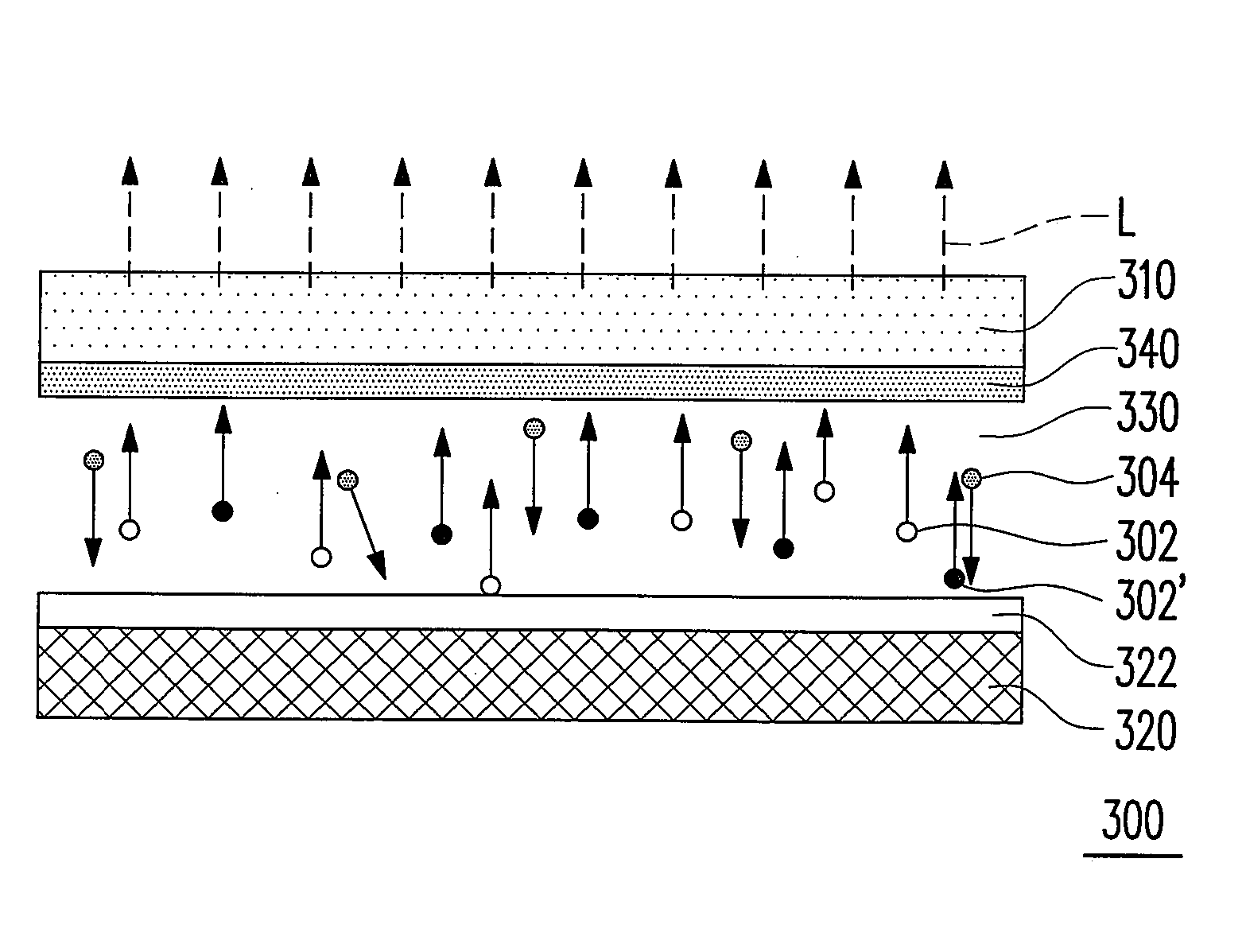
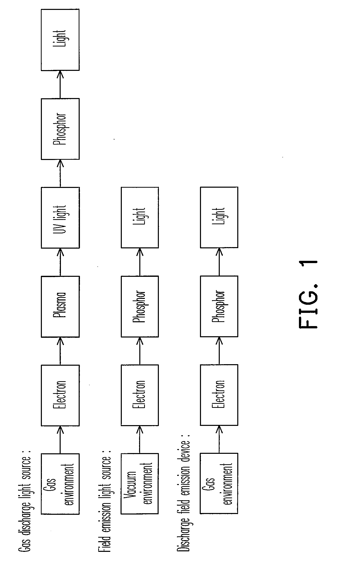
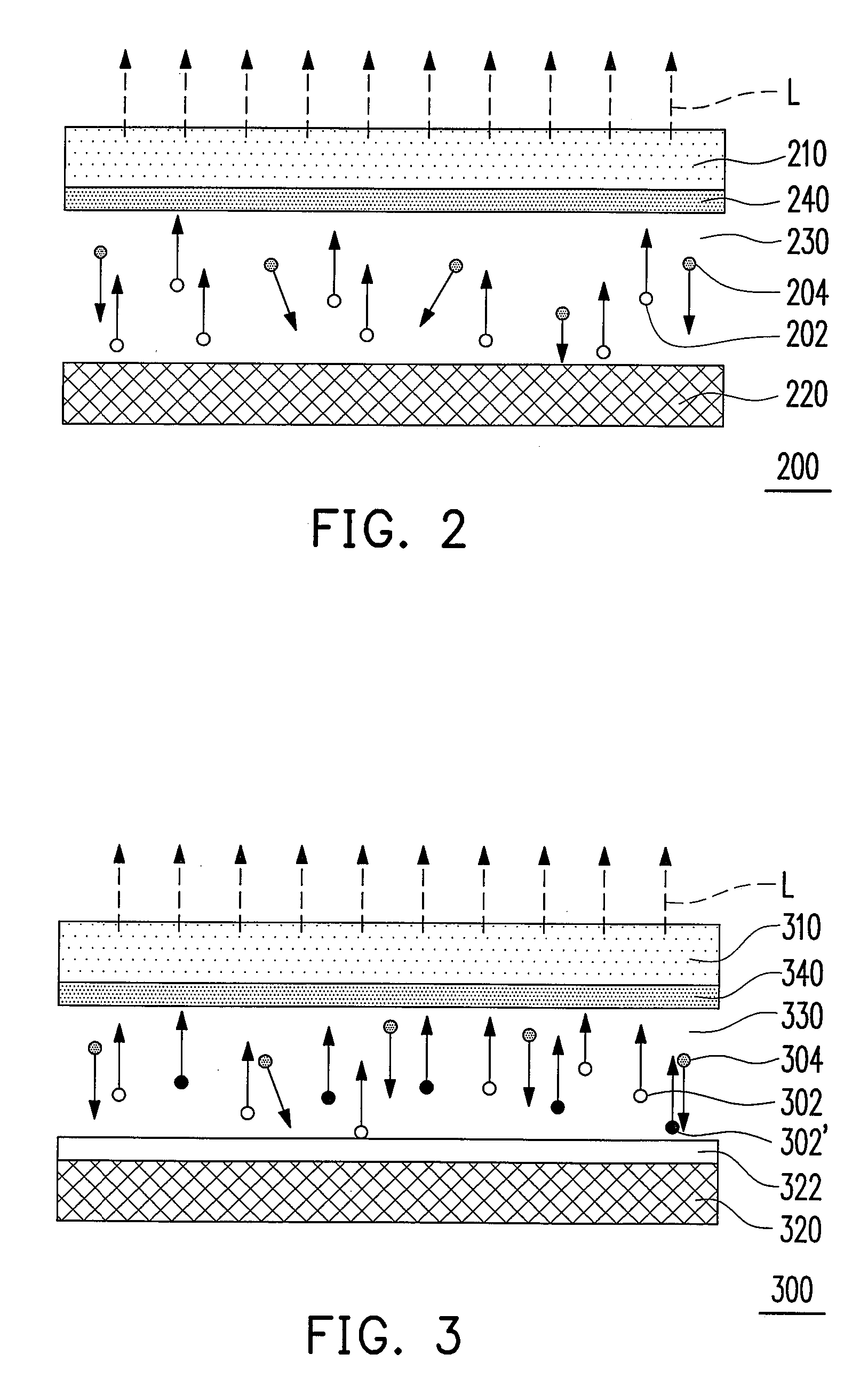
[0026]The discharge field emission device of the present invention has advantages of both the conventional gas discharge light source and the conventional field emission light source, and overcomes disadvantages of both aforementioned luminescence structures. FIG. 1 is a comparing diagram illustrating the luminescence mechanisms of the two aforementioned conventional luminescence structures and the discharge field emission device of the present invention. To be specific, in the conventional gas discharge light source, the gas that filled in discharge chamber is dissociated under the effect of the electric field between the cathode an the anode, and due to gas conduction, UV light is emitted when elec...


PUM


Abstract

A discharge field emission device including a cathode an anode, a conductive gas, and a phosphor is provided. The conductive gas is disposed between the cathode and the anode for inducing electrons from the cathode, wherein the conductive gas has a gas pressure between 10−1 torr and 10−3 torr. In addition, the phosphor is disposed on the moving path of the electrons to react with the electrons and emit light. The discharge field emission device has the advantages of high luminescence efficiency and low cost. A light source apparatus and a display apparatus applying the discharge field emission device are also provided.

Description

CROSS-REFERENCE TO RELATED APPLICATION[0001]This application claims the priority benefit of Taiwan application serial no. 95147427, filed Dec. 18, 2006. All disclosure of the Taiwan application is incorporated herein by reference.BACKGROUND OF THE INVENTION[0002]1. Field of the Invention[0003]The present invention relates to a luminescence device, more particularly, the present invention relates to a discharge field emission device and the application thereof.[0004]2. Description of Related Art[0005]Two main luminescence structures are applied in existing mass-produced light source apparatus or display apparatus, including:[0006]1. Gas discharge light source which may be applied to a plasma panel or a gas discharge lamp, wherein gas that filled in a discharge chamber is dissociated under the effect of an electric field between a cathode and an anode, and due to gas conduction, transition occurs and ultra violet (UV) light is emitted when electrons collide with gas, and phosphor in t...

Claims


Application Information

Patent Timeline
Patent Type & Authority Applications(United States)
IPC IPC(8): H01J1/62H01J63/02H01J63/04
CPCH01J61/62H01J63/08H01J63/06H01J1/30
Inventor LI, JUNG-YUCHEN, SHIH-PULIN, YI-PINGLIN, WEI-CHIHCHO, LIAN-YI
Owner IND TECH RES INST
Why Eureka
Try Eureka