
Method and apparatus for providing radiation shielding for non-invasive inspection systems

a technology of radiation shielding and inspection system, applied in the field of radiation shielding systems, can solve the problems of human tissue damage, slats from one strip curtain often entanglement the slats of one or more other strip curtains, and achieve the effects of reducing bag jams, improving baggage throughput, and simple and cost-effective manufacturing and installation

Active Publication Date: 2008-06-26
MORPHO DETECTION INC
View PDF10 Cites 23 Cited by
  • Summary
  • Abstract
  • Description
  • Claims
  • Application Information

AI Technical Summary

Benefits of technology

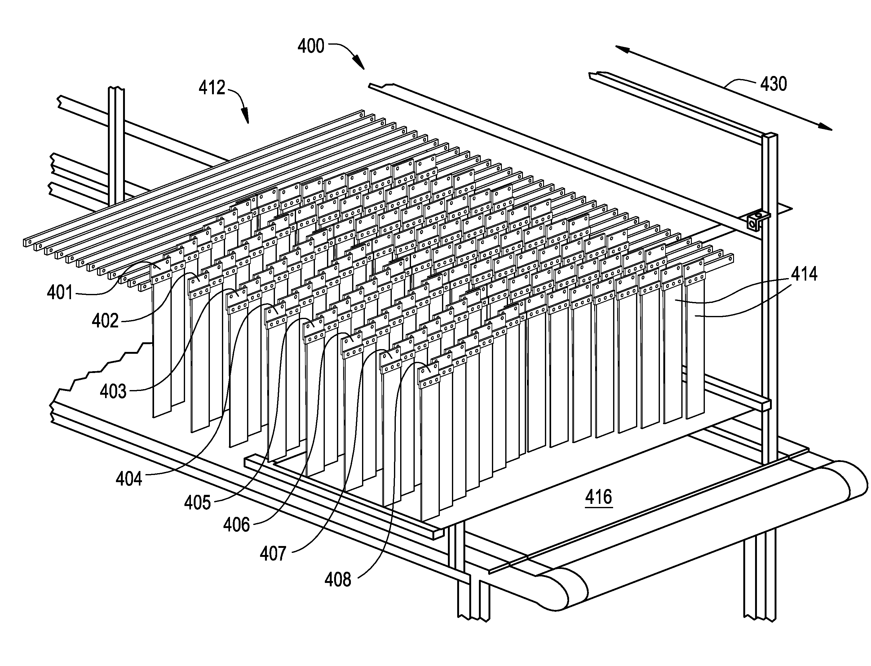
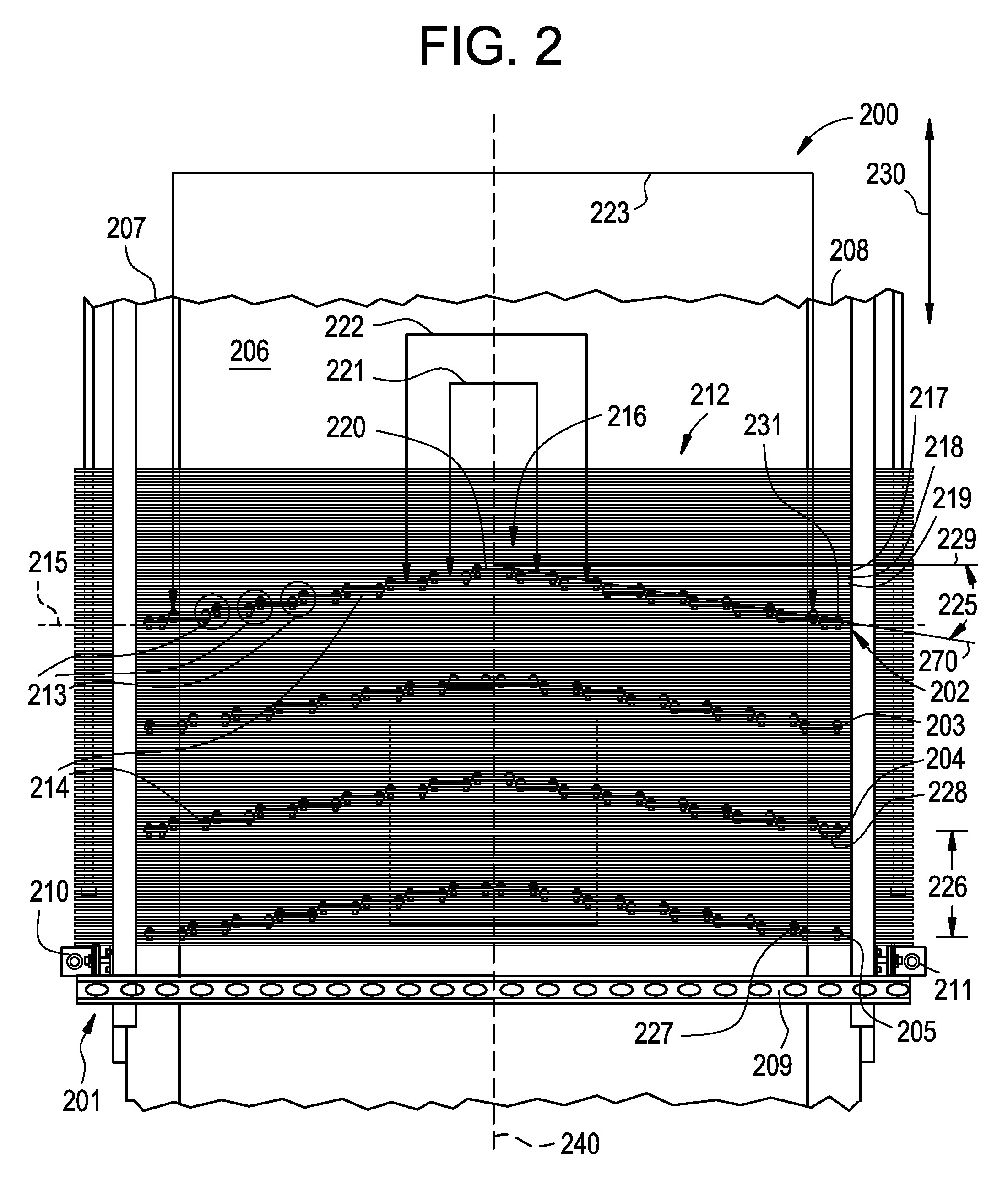
[0012]Relatively simple and cost-effective to manufacture and install, shielding curtains constructed and configured in accordance with embodiments of the present invention provide advantages that render them suitable for use in security applications, manufacturing applications, medical applications, etc. The solutions provided by such shielding curtains, and configurations thereof, afford several advantages, or technical effects. Illustratively, these advantages include, but are not limited to, significantly fewer bag jams, increased baggage throughput, reduced maintenance costs, and / or operating costs—all as compared with conventional shielding curtains and conventional shielding curtain configurations.
[0013]Embodiments of the invention increase baggage throughput by creating rows of non-planar passive shielding curtains. Each non-planar passive shielding curtains may comprise any suitable geometric shape. In one embodiment, each non-planar passive shielding curtain comprises slats of radiation-attenuating material arranged in a chevron-shape. The chevron configuration has at least two advantages. First, a chevron configuration reduces the number of slats that simultaneously contact a bag as the bag moves through the shielding curtain. The chevron configuration also reduces the force of the initial impact of the bag as it moves through the curtains and therefore reduces the occurrence of bag jams while still providing radiation protection. Reducing or eliminating the number of bag jams in this manner increases the number of bags a radiation-based inspection system can process in a given amount of time.
[0014]Many factors will affect the bag jam rate. Exemplary factors include, but are not limited to: whether the apex of the non-planar radiation shield is directed toward a scanning area or toward a portal through which bags enter or exit the scanner; the degree of the curtain angle; how many rows of shielding curtains will be used; how far apart the curtain rows are spaced from each other; and the height, weight, and width of the slats used to form each shielding curtain. In an embodiment of the invention, at least one or more of these exemplary factors is optimized to reduce the occurrence of bag jams.

Problems solved by technology

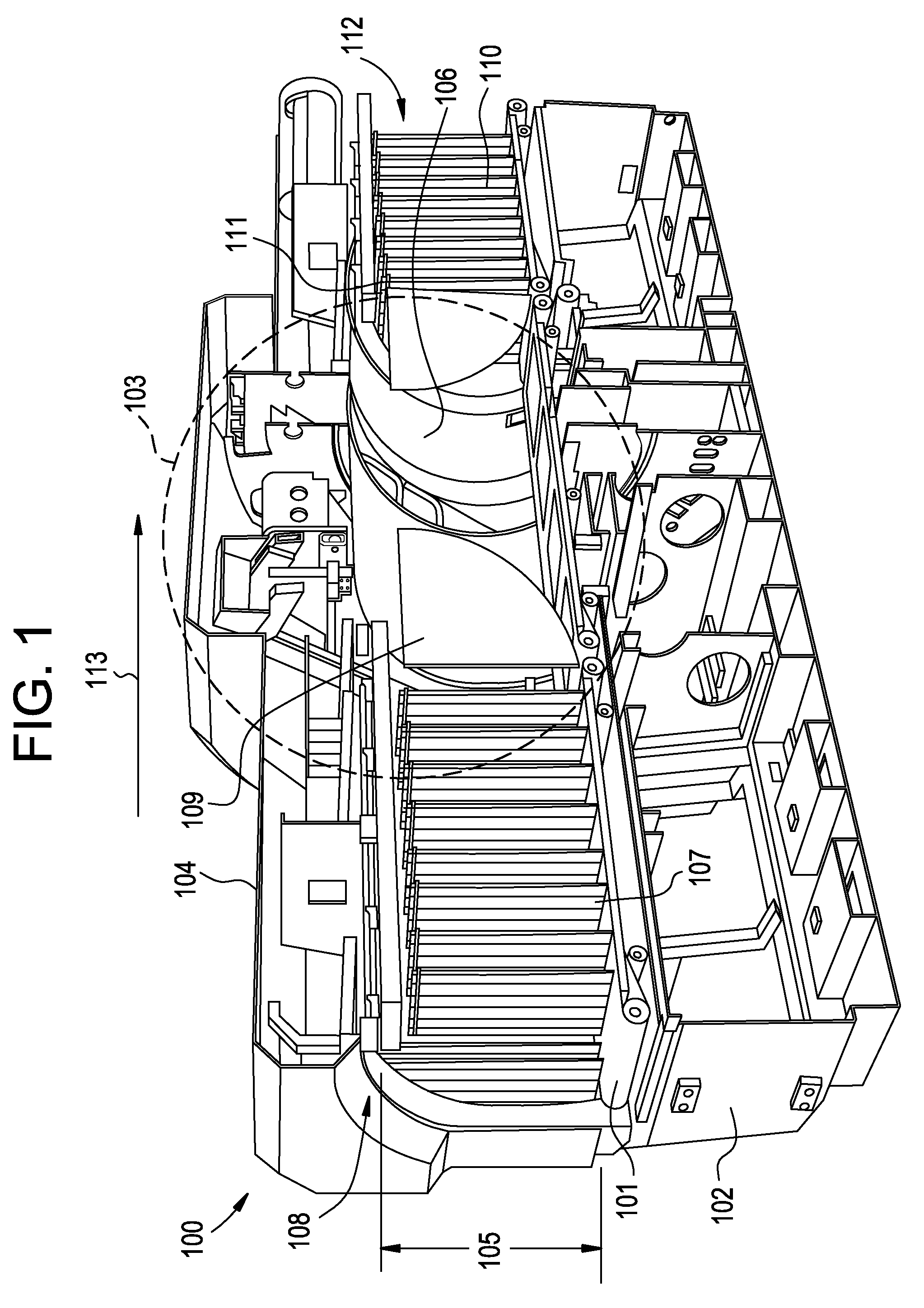
In certain types of inspection systems, such as explosive detection systems, one or more shielding curtains typically blocks the entrance and exit of an x-ray scanner, since highly concentrated dose of high-energy radiation from the scanner can damage human tissue if the dose is too high.
Chief among such disadvantages is that bags occasionally jam as they pass through the shielding curtains.
When shielding curtains are arranged in parallel, planar rows, jamming occurs because most or all of the slats will contact a bag simultaneously, which traps the bag(s) in the strip curtain(s) even though the conveyor belt supporting the bag(s) continues to move.
Another disadvantage associated with conventional strip curtains, such as those illustrated in FIG. 1, is that the slats from one strip curtain often entangle the slats of one or more other strip curtains.

Method used


Image

  • Method and apparatus for providing radiation shielding for non-invasive inspection systems
  • Method and apparatus for providing radiation shielding for non-invasive inspection systems
  • Method and apparatus for providing radiation shielding for non-invasive inspection systems

Examples


Embodiment Construction

[0027]Reference is made herein to the accompanying drawings briefly described above, which show by way of illustration various embodiments of the invention. Persons of ordinary skill in the above-referenced technological field will recognize that other embodiments may be utilized, and that various changes may be made without departing from the scope of the claimed invention.

[0028]As used herein, an element or step recited in the singular and proceeded with the word “a” or “an” includes plural elements or steps, unless exclusion of such plural elements or steps is explicitly recited.

[0029]FIG. 2 is a top view of an embodiment of a radiation shield having four strip curtains, each arranged in a non-planar shape. Any type of non-planar (e.g., three-dimensional) shape may be used, a non-limiting example of which is a chevron-shape. As used herein, “chevron-shape” refers to a “V,”“U,” inverted “V,” or inverted “U” arrangement of radiation shielding material. As used herein, “radiation sh...


PUM

PropertyMeasurementUnit
Angleaaaaaaaaaa
Angleaaaaaaaaaa
Shapeaaaaaaaaaa

Abstract

Disclosed herein is a method and apparatus for providing radiation shielding for non-invasive inspection systems. An embodiment of the apparatus may include a radiation shield having a plurality of slats, where each of the plurality of slats comprises a radiation attenuating material. The radiation shield may further include a support structure configured to hold the slats in a non-planar shape. An embodiment of the method may include gathering a plurality of slats, each slat comprising a radiation attenuating material. The method may further include disposing the slats to form a shielding curtain having a non-planar shape. The method may also include positioning the shielding curtain to cover an opening of a scanner.

Description

BACKGROUND[0001]1. Field of the Invention[0002]The technology disclosed herein relates to radiation shielding systems generally, and more particularly, to a method, apparatus, and system for providing radiation shielding for non-invasive inspection systems.[0003]2. Discussion of Related Art[0004]Explosive detection systems and other types of inspection systems typically use radiation-based scanners, such as x-ray line scanners, x-ray CT scanners, and coherent x-ray scatter scanners, to examine bags (pieces of passenger baggage) for the presence of one or more alarm objects (explosives, weapons, illegal drugs, contraband, product components, and the like). In certain types of inspection systems, such as explosive detection systems, one or more shielding curtains typically blocks the entrance and exit of an x-ray scanner, since highly concentrated dose of high-energy radiation from the scanner can damage human tissue if the dose is too high. Some shielding curtains (hereinafter, “shee...

Claims


Application Information

Patent Timeline
IPC IPC(8): G21F3/00B23P11/00B23P15/00
CPCA61B6/107Y10T29/49826G21F3/00G21F1/12
Inventor HARGROVE, RICHARD OLIVER
Owner MORPHO DETECTION INC
Learn More