Current-controlling apparatus

Active Publication Date: 2008-06-26
CPT TECH GRP
View PDF10 Cites 37 Cited by
  • Summary
  • Abstract
  • Description
  • Claims
  • Application Information

AI Technical Summary

Benefits of technology

[0019]The present invention uses the current of the LEDS as a feedback control, performs a current compensation on the current of the LEDS and converts the compensated current into two signals to control the impedance of the MOS transistor in on status (i.e. to control the channel size of the MOS transistor in on status). In this way, i.e. adjustin

Problems solved by technology

Such a design not only reduces the set number of the driving ICs, but also lowers the total driving current of the LEDs and further lowers the consumption power of the driving ICs.
However, it is difficult to make the cut-in voltage (standing for the lowest voltage to turn on an LED) of every LED completely consistent with each other in an LED manufacturing process.
Consequently, the error values for the cut-in voltage of every LED would be accumulated, which results in difference between the currents of each LED string set due to the inconsistent cut-in voltages under a constant input voltage.
Therefore, a phenomenon of uneven brightness or uneven chrominance appears on the backlight source of a display panel.
Theref

Method used


Image

  • Current-controlling apparatus
  • Current-controlling apparatus
  • Current-controlling apparatus

Examples


Example

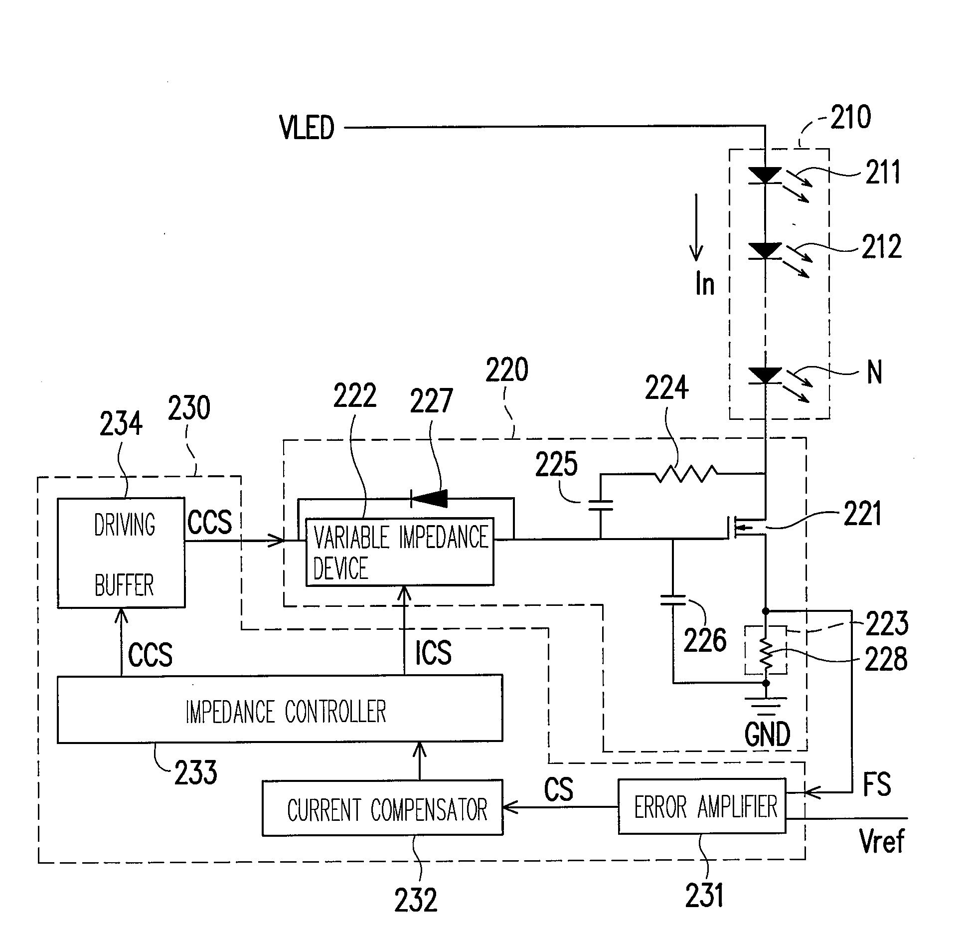
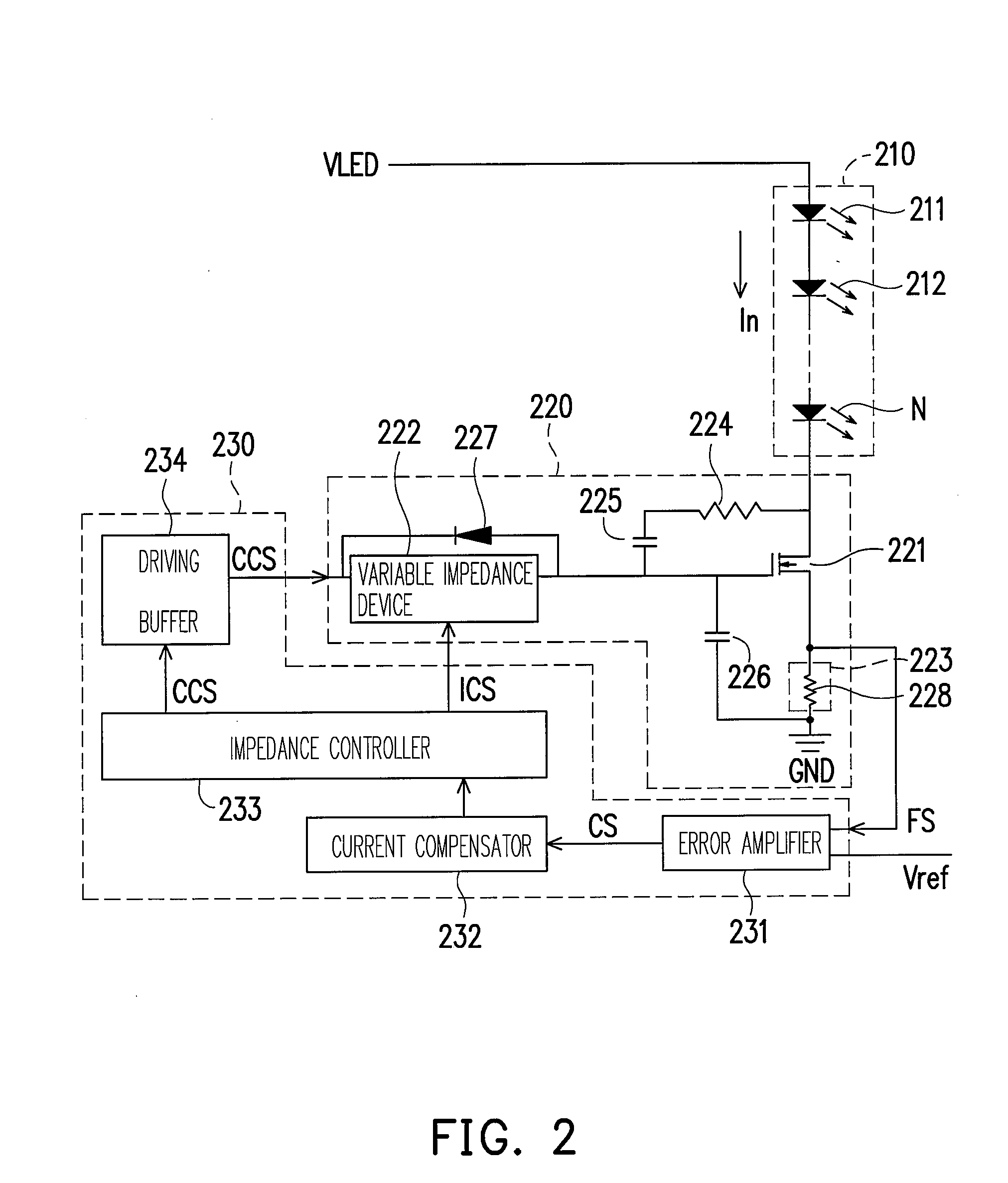
[0026]FIG. 2 is a current-controlling apparatus according to an embodiment of the present invention. Referring to FIG. 2, the current-controlling apparatus is suitable for controlling the current In passing through the LEDS 210. In the embodiment, the LEDS 210 is formed by LEDs 211, 212˜N and an end of the LEDS 210 is electrically connected to a power voltage VLED (i.e. a first voltage level). The present invention, however, does not limit the LEDS 210 to be formed by LEDs only.

[0027]The current-controlling apparatus includes a current-adjusting unit 220 and a control unit 230. The current-adjusting unit 220 is used for detecting the current In of the LEDS 210, producing a feedback signal FS hereby and controlling the impedance between the LEDS 210 and the grounding voltage GND (i.e. the second voltage level) according to a conductance-controlling signal CCS and an impedance-controlling signal ICS, and further controlling the current In of the LEDS 210. The control unit 230 is used ...


PUM


Abstract

A current-controlling apparatus is suitable for controlling the current passing through a light emitting device string (LEDS), wherein an end of the LEDS is electrically connected to a first-voltage level. The current-controlling apparatus includes a current-adjusting unit and a control unit. The current-adjusting unit, electrically connected between a second-voltage level and another end of the LEDS, is used for detecting a current of the LEDS, producing a feedback signal hereby and controlling the impedance between the LEDS and the second voltage level according to a conductance-controlling signal and an impedance-controlling signal to control the current. The control unit is electrically connected to the current-adjusting unit for receiving a reference signal and the feedback signal, comparing the feedback signal with the reference signal to give a comparison result, performing a current compensation on the comparison result and converting the compensated comparison result into the conductance-controlling signal and the impedance-controlling signal.

Description

BACKGROUND OF THE INVENTION[0001]1. Field of Invention[0002]The present invention relates to a current-controlling apparatus, and more particularly, to a current-controlling apparatus using a feedback control to adjust the current passing through a light emitting diode string (LED string) for adjusting the brightness of the LED string.[0003]2. Description of the Related Art[0004]For a backlight source implemented in LED mode of a liquid crystal display television (LCD television), a large number of LEDs are employed to make the backlight source match a cold cathode fluorescent lamp (CCFL) in terms of the brightness thereof. In order to reduce the number of the driving integrated circuits (driving IC) for the LEDs and lower the total driving current of the LEDs, the circuit of the backlight source is usually designed by employing multiple LEDs in series connection for lightening the same. Such a design not only reduces the set number of the driving ICs, but also lowers the total driv...

Claims


Application Information

Patent Timeline
IPC IPC(8): G09G3/36
CPCG09G3/32G09G3/3406H05B33/0851H05B33/0827G09G2320/041H05B45/46H05B45/10
Inventor CHAO, HAN-YUCHEN, BI-HSIENLIN, SHIN-CHANG
Owner CPT TECH GRP
Why Eureka
Try Eureka