Liquid-crystal optical element, camera using the same, and optical pickup device using the same

a technology of liquid crystal and optical element, which is applied in the field of liquid crystal optical element, camera using the same, optical pickup device using the same, etc., can solve the problems of increasing the number of pixels of digital cameras, increasing the density of information recording media, and inevitably causing information recording or reproduction errors. , to achieve the effect of facilitating the isolation between the contact electrode and the segment electrod

Inactive Publication Date: 2008-06-26
CITIZEN WATCH CO LTD
View PDF2 Cites 29 Cited by
  • Summary
  • Abstract
  • Description
  • Claims
  • Application Information

AI Technical Summary

Benefits of technology

[0019]According to the present invention, a contact electrode that is connected to that one of each two adjacent segment electrodes which is situated on the liquid crystal layer side is connected to the destination segment electrode inside its edge, whereby insulation between the contact electrode and the segment electrode can be facilitated.
[0020]Further, the wiring electrodes that are connected electrically to the segment electrodes, individually, are formed between the first transparent substrate and the segment elec

Problems solved by technology

If the optical element is used as an aberration correcting optical element, on the other hand, an information recording or reproduction error is inevitably caused owing to a failure of aberration correction.
These problems have become serious with the increase of the number of pixels of digital cameras and the density of information recording medi

Method used


Image

  • Liquid-crystal optical element, camera using the same, and optical pickup device using the same
  • Liquid-crystal optical element, camera using the same, and optical pickup device using the same
  • Liquid-crystal optical element, camera using the same, and optical pickup device using the same

Examples


first embodiment

[0045]A liquid-crystal optical element according to the present invention will be described with reference to FIGS. 1A to 5.

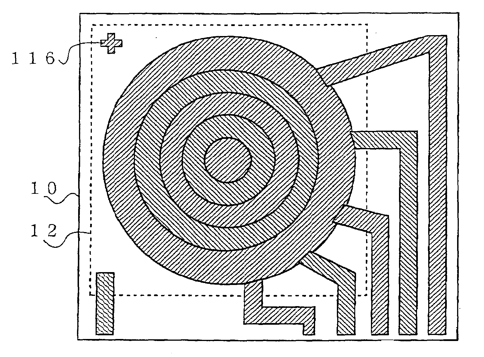
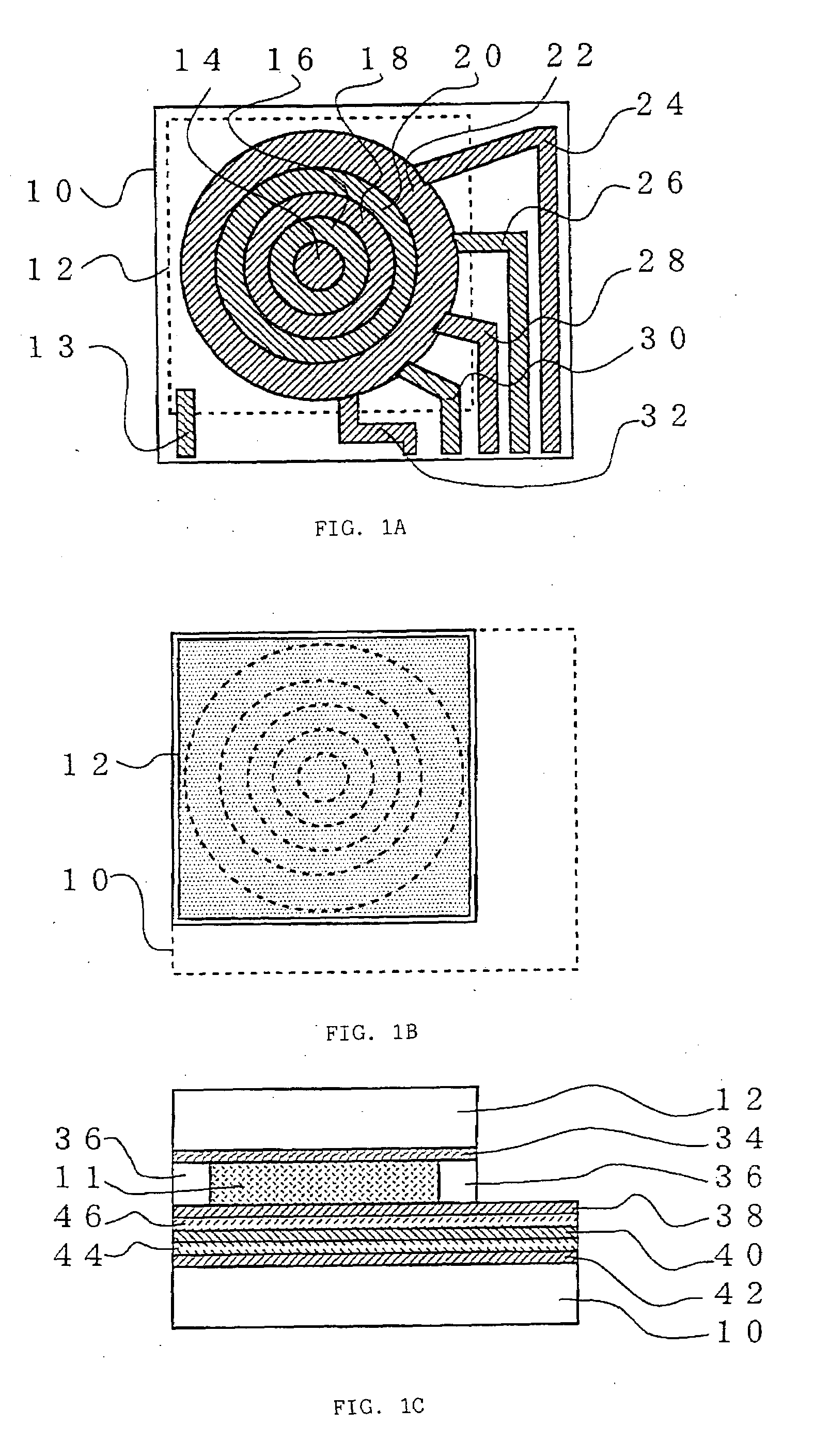
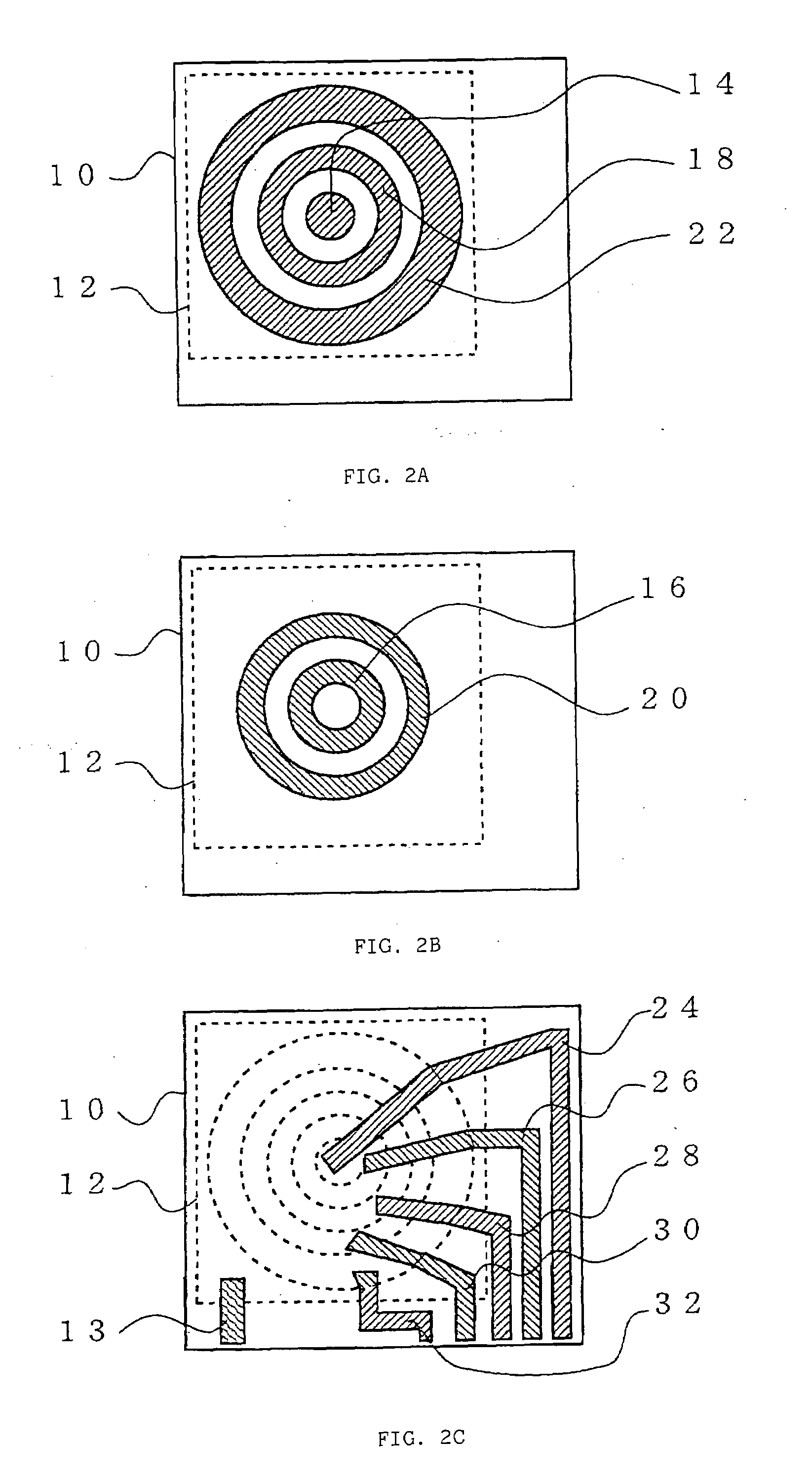
[0046]As shown in FIG. 1A, concentrically arranged ring-shaped segment electrodes 14, 16, 18, 20 and 22 and wiring electrodes 24, 26, 28, 30 and 32 that apply driving signals to the segment electrodes are formed on a larger transparent substrate 10 that constitutes the liquid-crystal optical element. Each ring-shaped segment electrode is connected to its corresponding wiring electrode in a contact portion (mentioned later). The segment electrodes 14, 16, 18, 20 and 22 are arranged without clearances when viewed in the direction perpendicular to the planes of the transparent substrates 10 and 12. Also formed is a common terminal electrode 13 for applying a driving signal to an electrode on the smaller transparent substrate 12.

[0047]As shown in FIG. 1B, a transparent electrode is formed on the whole surface of the smaller transparent substrate 12 that constitutes...

second embodiment

[0076]A liquid-crystal optical element according to the present invention will be described with reference to FIGS. 6A and 6B.

[0077]As shown in FIG. 6A, a first insulating layer 44 is provided on a wiring electrode 24 on a first transparent electrode layer, while a second insulating layer 46 is provided on a segment electrode 16 on a second transparent electrode layer and in a center space of the segment electrode 16. Ring-shaped segment electrodes 14 and 18 on a third transparent electrode layer are located on an uppermost layer, and a transparent conductor 70 is formed in a contact portion between the wiring electrode 24 and the segment electrode 14.

[0078]The present embodiment is characterized in that the second insulating layer 46 is left on the segment electrode 16 on the second transparent electrode layer. By thus leaving the insulating layer on the segment electrode on the second transparent electrode layer, a step of removing the second insulating layer 46 can be omitted, so...

third embodiment

[0084]A liquid-crystal optical element according to the present invention will be described with reference to FIGS. 7A to 7E.

[0085]In the present embodiment, as shown in FIGS. 7A to 7E, insulating layers are made thicker than transparent electrode layers, as in the case of the second embodiment shown in FIGS. 6A and 6B.

[0086]FIG. 7A is a sectional view in which a wiring electrode 24 (first transparent electrode layer), a first insulating layer 44, and a transparent conductor 70 in a contact portion are formed on a transparent substrate 10.

[0087]In conventional processes, a second transparent electrode layer is formed subsequent to the process of FIG. 7A, and thereafter, the second transparent electrode layer is patterned by etching. In the manufacture of the liquid-crystal optical element according to the present embodiment, however, a second insulating layer 46 is formed in the manner shown in FIG. 7B.

[0088]Then, as shown in FIG. 7C, adjacent ring-shaped segment electrodes are form...


PUM


Abstract

A liquid-crystal optical element comprises a plurality of wiring electrodes formed between a plurality of segment electrodes and a lower transparent substrate and connected electrically to the segment electrodes, individually, and a plurality of contact electrodes connected to the segment electrodes and the corresponding wiring electrodes. The adjacent segment electrodes are different in height position above the lower transparent substrate. A contact electrode that is connected to that one of each two adjacent segment electrodes which is situated on the side of a liquid crystal layer is connected to the destination segment electrode inside its edge, when viewed along a section formed by cutting the segment electrode in the direction perpendicular to the planes of the lower and an upper transparent substrate.

Description

BACKGROUND OF THE INVENTION[0001]1. Field of the Invention[0002]The present invention relates to a liquid-crystal optical element used as an aberration correcting optical element for aberration correction for information recording and reproduction using an information recording medium, such as a variable-focus lens of a digital camera, optical disc, etc., a camera using the liquid-crystal optical element as a lens, and an optical pickup device using the liquid-crystal optical element.[0003]2. Description of the Related Art[0004]A conventionally known liquid-crystal optical element, such as the one shown in FIGS. 19A and 19B, is used as an aberration correcting optical element for aberration correction for information recording and reproduction using an information recording medium, such as a variable-focus lens of a digital camera, optical disc, etc.[0005]FIGS. 19A and 19B are a plan view and a sectional view, respectively, showing principal electrodes of the liquid-crystal optical ...

Claims


Application Information

Patent Timeline
IPC IPC(8): G02F1/1343
CPCG02B3/14G02B26/004G02F1/134309H04N5/2254G11B7/1378G11B7/13927G02F2001/294G02F1/294
Inventor SEKIGUCHI, KANETAKA
Owner CITIZEN WATCH CO LTD
Why Eureka
Try Eureka