Electrostatic ultrasonic transducer, and ultrasonic speaker, audio signal reproduction method, ultra-directive sound system, and display apparatus using electrostatic ultrasonic transducer

a transducer and electrostatic technology, applied in the direction of frequency response correction, generator/motor, mechanical vibration separation, etc., can solve the problems of speed increase, difficult to achieve the electrostatic-type ultrasonic transducer level, and distortion of modulated waves, so as to achieve the effect of improving the sound pressure characteristics, reducing the distortion, and reducing the distortion

Inactive Publication Date: 2008-06-26
SEIKO EPSON CORP
View PDF3 Cites 33 Cited by
  • Summary
  • Abstract
  • Description
  • Claims
  • Application Information

AI Technical Summary

Benefits of technology

[0069]According to this structure, the sound signals having sufficient sound pressure and broadband characteristics can be generated from a virtual sound source formed in the vicinity of a sound wave reflection surface such as...

Problems solved by technology

In this case, the sound speed increases in the condensed part and decreases in the rarefractional part, and thus distortion of the modulated waves is caused.
However, the electrostatic-type ultrasonic transducer is difficult to achieve this level, and a ceramic piezoelectric element such as PZT and a high molecular piezoelectric element such as PVDF are generally used as ultrasonic wave generator.
Thus, the frequency range at which high sound pressure can be secured is extremely narrow.
In case of the ultrasonic speaker, therefore, it is difficult to precisely demodulate the original audio signals when high sound pressure is not secured throughout the frequency band of 20 kHz in the ultrasonic wave range.
However, it is easily understood that precise reproduction (demodulation) in the wide band range throughout 20 kHz is extremely difficult for the resonance-type ultrasonic speaker using the piezoelectric element in the related art.
Actually, the following problems have been arisi...

Method used


Image

  • Electrostatic ultrasonic transducer, and ultrasonic speaker, audio signal reproduction method, ultra-directive sound system, and display apparatus using electrostatic ultrasonic transducer
  • Electrostatic ultrasonic transducer, and ultrasonic speaker, audio signal reproduction method, ultra-directive sound system, and display apparatus using electrostatic ultrasonic transducer
  • Electrostatic ultrasonic transducer, and ultrasonic speaker, audio signal reproduction method, ultra-directive sound system, and display apparatus using electrostatic ultrasonic transducer

Examples


first embodiment

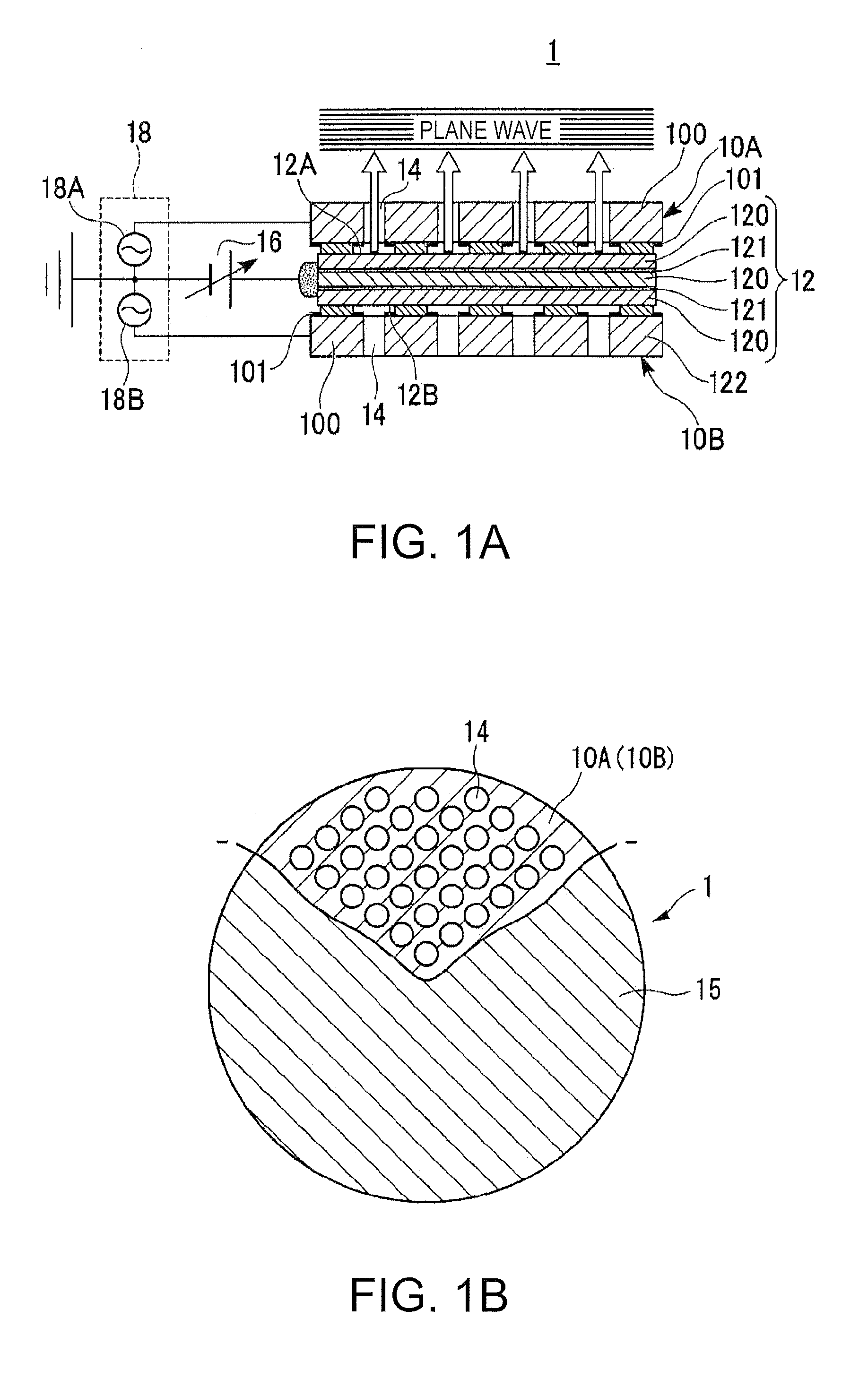
[0086]FIGS. 1A and 1B illustrate a structure of an electrostatic ultrasonic transducer according to the invention. FIG. 1A shows the structure of the electrostatic ultrasonic transducer, and FIG. 1B is a plan view of the ultrasonic transducer a part of which is cut away.

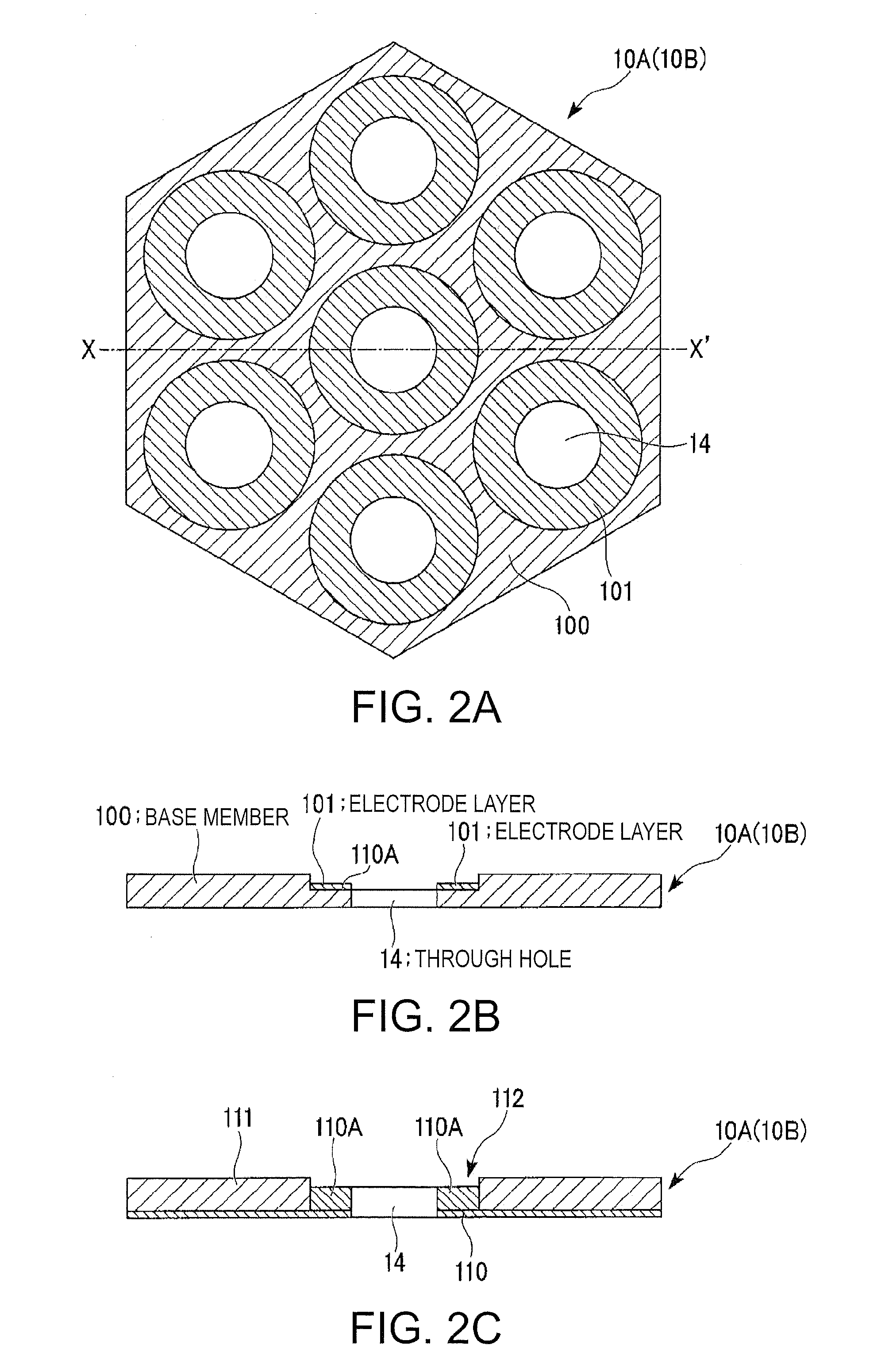
[0087]As illustrated in FIGS. 1A and 1B, an electrostatic ultrasonic transducer 1 according to the first embodiment of the invention includes a fixed electrode 10A (first electrode) having through holes 14, a fixed electrode 10B (second electrode) having through holes each of which is paired with the corresponding one of the through holes 14 of the fixed electrode 10A, an oscillation film 12 sandwiched between the pair of the fixed electrodes 10A and 10B and having electrode layers 121, and a holding member (not shown) for holding the pair of the fixed electrodes 10A and 10B and the oscillation film.

[0088]The oscillation film 12 has an insulator (insulation layer) 120. The electrode layers 121 made of conductive mate...

second embodiment

[0116]FIG. 3C illustrates the cross-sectional structure of the electrode taken along the line Y-Y′ in FIG. 3A according to another example (modified example of second embodiment). As illustrated in FIGS. 1A and 1B and FIG. 3C, base members 210 of the pair of the fixed electrodes 10A and 10B included in the electrostatic ultrasonic transducer 1 are made of conductive material. The base member 210 of each of the pair of the fixed electrodes 10A and 10B has an electrode portion 210A formed in the bridge shape and disposed in such a position as to be opposed to the electrode layers 121 of the oscillation film 12. The electrode portion 210A is an area as the only convex portion on which electrostatic force acts to increase the distance from the electrode layer 121 of the oscillation film 12. Each of the pair of the fixed electrodes 10A and 10B also has a non-conductive portion 211 on which through holes 212 are formed. The base member 210 and the non-conductive portion 211 can be combine...


PUM


Abstract

An electrostatic ultrasonic transducer includes a first electrode having a through hole, a second electrode having a through hole, and an oscillation film disposed such that the through hole of the first electrode can be paired with the through hole of the second electrode and sandwiched between the pair of the first electrode and second electrode. The oscillation film has an electrode layer to which direct current bias voltage is applied. Each of the pair of the electrodes has an electrode portion at a position in the periphery of the through hole. An alternating current signal is applied between the pair of the electrodes and the electrode layer of the oscillation film.

Description

BACKGROUND[0001]1. Technical Field[0002]The present invention relates to an electrostatic ultrasonic transducer which has high directivity and produces constant high sound pressure throughout a wide frequency band range, and an ultrasonic speaker having high directivity, an audio signal reproduction method, an ultra-directive sound system, and a display apparatus which use this electrostatic ultrasonic transducer.[0003]2. Related Art[0004]Most ultrasonic transducers as sound emitting apparatuses having high directivity in related art are of resonance type which use piezoelectric ceramic.[0005]FIG. 9 illustrates a structure of an ultrasonic transducer in related art. Most ultrasonic transducers in related art are of resonance type which use piezoelectric ceramic as oscillation element. The ultrasonic transducer shown in FIG. 9 uses piezoelectric ceramic as the oscillation element to perform both conversion from electric signals to ultrasonic waves and conversion from ultrasonic waves...

Claims


Application Information

Patent Timeline
IPC IPC(8): H04R3/06H04R3/00H04R19/02
CPCB06B1/0292
Inventor MATSUZAWA, KINYA
Owner SEIKO EPSON CORP
Why Eureka
Try Eureka