
Solid oxide fuel cell power generator

a technology of solid oxide fuel cell and power generator, which is applied in the manufacture of cell components, electrochemical generators, and final product manufacturing, etc., can solve the problems of power generator, difficult to improve the durability of solid oxide fuel cells, and inability to meet the needs of power generation, etc., to achieve low manufacturing cost and high power generation density.

Inactive Publication Date: 2008-06-26
SHINKO ELECTRIC IND CO LTD
View PDF4 Cites 11 Cited by
  • Summary
  • Abstract
  • Description
  • Claims
  • Application Information

AI Technical Summary

Benefits of technology

[0014]Therefore, it is an object of the invention to provide an open type solid oxide fuel cell power generator in which a collecting structure is simple, a manufacturing cost is low, a electrically parallel or serial connection can easily be carried out, and a power generating density is high.
[0022]As described above, according to the solid oxide fuel cell power generator in accordance with the invention, a collecting structure is electrically simple, a manufacturing cost is low, a parallel or serial connection can easily be carried out and a power generating density is high.

Problems solved by technology

In addition, it is inevitable for those chambers to be exposed to an oxidizing atmosphere and a reducing atmosphere at a high temperature.
For these reasons, it is said that such a power generator is difficult to improve its durability of the solid oxide fuel cell.
However, as for the power generator using the solid oxide fuel cell of the single type chamber, its driving operation is eventually required to be carried out at a high temperature of approximately 1000° C. For this reason, there is a risk of an explosion of the mixed fuel gas.
However, in this case, there is a problem in that a fuel, such as methane, is more likely to be carbonized so that a cell performance is deteriorated.
For this reason, the solid oxide fuel cell power generator having the single type chamber using the plate-shaped solid oxide fuel cell becomes a large-scaled structure, which ends up being a problem of increased cost.
In this regard, the start timing of an electromotive operation is prolonged, which might be practically inefficient.

Method used


Image

  • Solid oxide fuel cell power generator
  • Solid oxide fuel cell power generator
  • Solid oxide fuel cell power generator

Examples


first embodiment

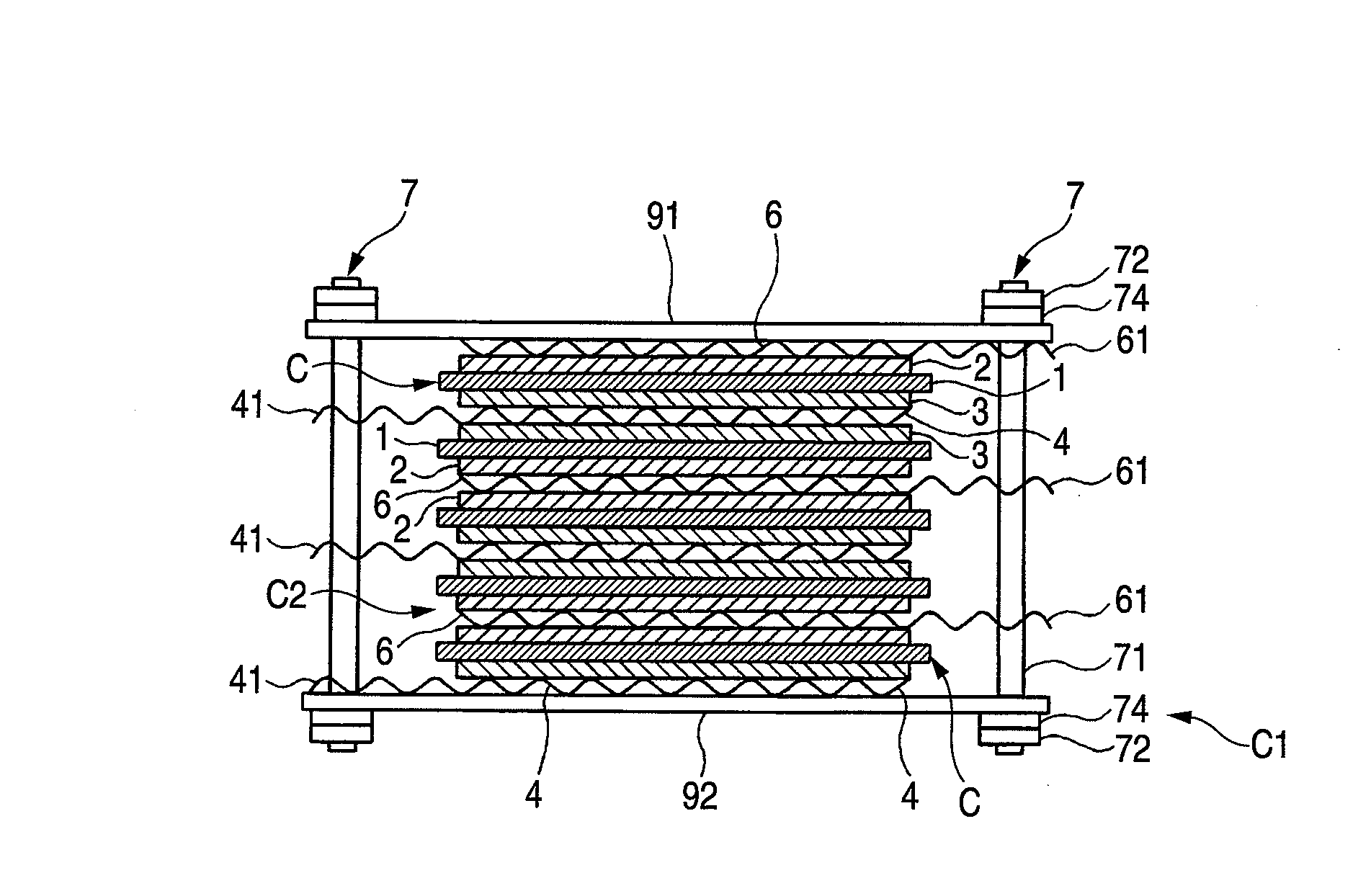
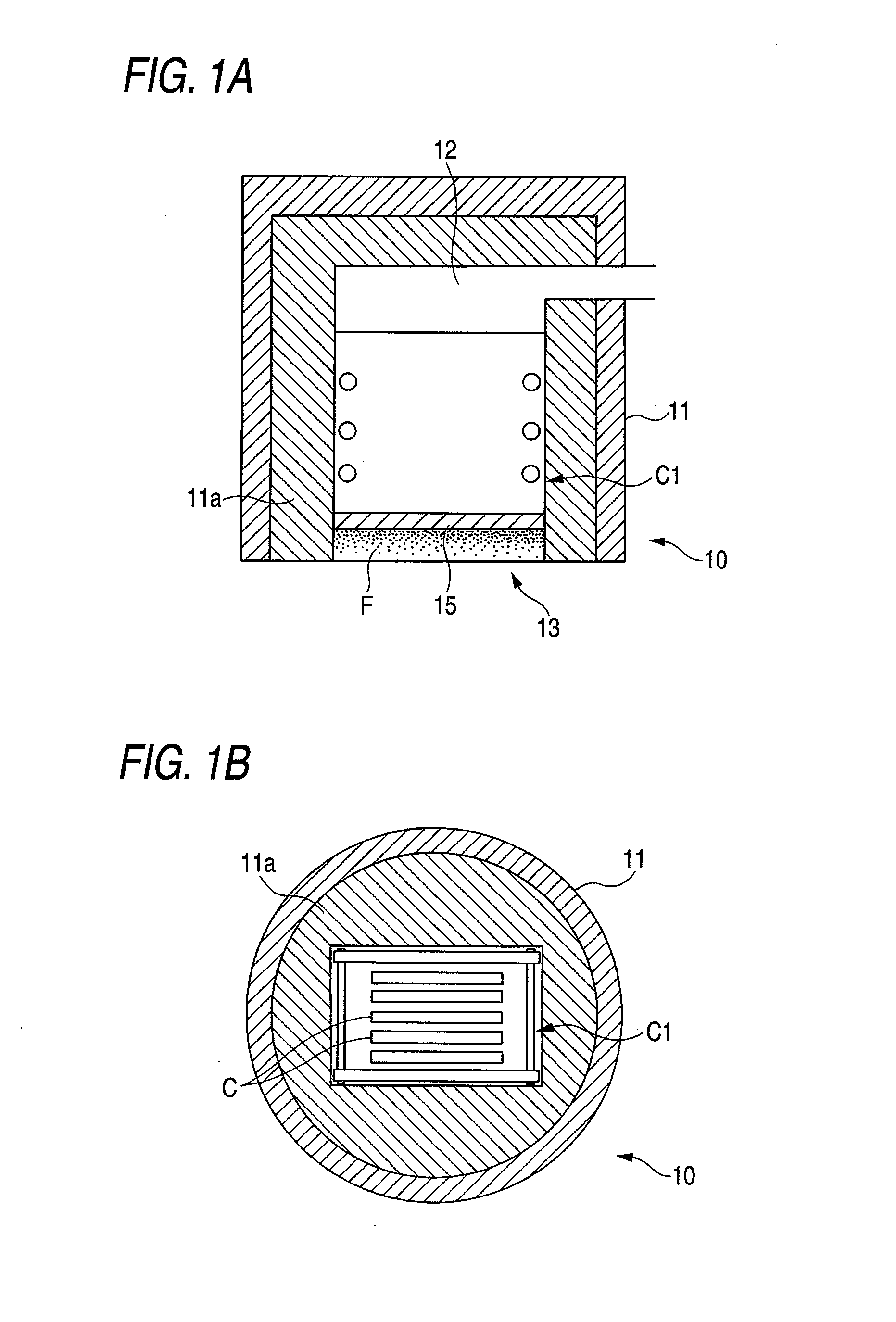
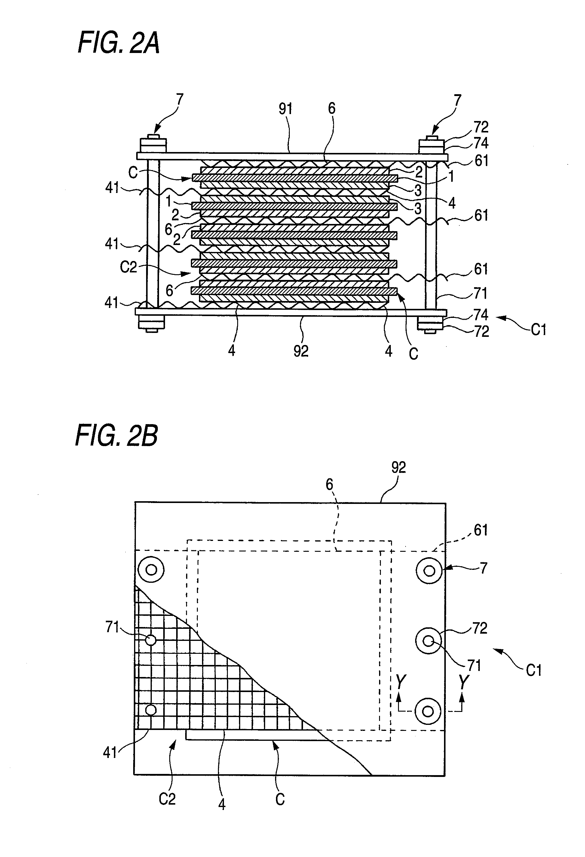
[0035]A solid oxide fuel cell power generator 10 according to the embodiment (which will be hereinafter referred to as the apparatus) comprises a plurality of solid oxide fuel cells C in which a cathode electrode layer 2 and an anode electrode layer 3 are formed on both sides of a solid electrolytic substrate 1 as shown in FIGS. 1 to 6.

[0036]In the apparatus 10, moreover, the solid oxide fuel cells C are disposed in such a manner that the respective anode electrode layers 3 of the adjacent solid oxide fuel cells C are opposed to each other. A first electric conductor 4 having a gas permeability is interposed between the opposed anode electrode layers 3 in contact with the respective anode electrode layers 3. The first electric conductor 4 has a first extended portion 41 which is extended beyond each of the anode electrode layers 3. The first electric conductor 4 serves as a collector of the anode electrode layer 3.

[0037]As shown in FIG. 1, the apparatus 10 comprises a fuel cell unit...

second embodiment

[0120]A solid oxide fuel cell power generator 10 according to a second preferred embodiment of the invention is shown in FIG. 7. As shown in an example of FIG. 7, a plate-shaped third electric conductor 8 having a gas permeability is interposed between a first electric conductor 4 and an anode electrode 3 positioned on both sides thereof in the apparatus 10. Similarly, the plate-shaped third electric conductor 8 having the air permeability is interposed between a second electric conductor 6 and a cathode electrode layer 2 positioned on both sides thereof. In a fuel cell stack C2 of the apparatus 10, the third electric conductor 8 is interposed between the first electric conductor 4 and the anode electrode layer 3 and between the second electric conductor 6 and the cathode electrode layer 2 at both sides of a solid oxide fuel cell C which is stacked, respectively.

[0121]In FIG. 7, for easy understanding of the structure of the apparatus 10, a pair of support plates and fixing means ar...

third embodiment

[0131]A solid oxide fuel cell power generation system employing the solid oxide fuel cell power generator 10 according to a third preferred embodiment of the invention is shown in FIG. 8. FIG. 8is a top view showing three fuel cell stacks. In the embodiment, there are provided three fuel cell stacks C2a, C2b and C2c as shown in an example of FIG. 8. A plurality of first extended portions 41 and a plurality of second extended portions 61 have a first connector 42 and a second connector 62, respectively. The first extended portions 41 are electrically connected to each other through the first connector 42. Similarly, the second extended portions 61 are electrically connected to each other through the second connector 62.

[0132]The three fuel cell stacks C2a, C2b and C2c are disposed. The three fuel cell stacks C2a, C2b and C2c are electrically connected in series through the first connectors 42 and the second connectors 62 therein.

[0133]Each of the three fuel cell stacks C2a, C2b and C...


PUM

PropertyMeasurementUnit
driving temperatureaaaaaaaaaa
temperatureaaaaaaaaaa
diameteraaaaaaaaaa

Abstract

A solid oxide fuel cell power generator according to the invention includes a plurality of solid oxide fuel cells C having a cathode electrode layer 2 and an anode electrode layer 3 formed on both sides of a solid electrolytic substrate 1, and the solid oxide fuel cells C are disposed in such a manner that the respective anode electrode layers 3 of the adjacent solid oxide fuel cells C are opposed to each other. A first electric conductor 4 having a gas permeability is interposed between the opposed anode electrode layers 3 in contact with the anode electrode layers 3. The first electric conductor 4 has a first extended portion 41 which is extended beyond each of the anode electrode layers 3, and serves as a collector of the anode electrode layer 3.

Description

BACKGROUND OF THE INVENTION[0001]1. Field of the Invention[0002]The present invention relates to a solid oxide fuel cell power generator, and more particularly to a solid oxide fuel cell power generator having a structure in which a solid oxide fuel cell including a solid electrolytic substrate having a cathode electrode layer and an anode electrode layer formed thereon is provided and a closure is not required.[0003]2. Description of the Related Art[0004]In recent years, various fuel cells of a power generating type have been developed, including a solid oxide fuel cell where a solid electrolyte is employed. As an example of the solid oxide fuel cell, a burned product constituted by stabilized zirconia having yttria (Y2O3) added thereto is used as a solid electrolytic layer of an oxygen ion conducting type. A cathode electrode layer is formed on one of surfaces of the solid electrolytic layer while an anode electrode layer is formed on an opposite surface thereto, and oxygen or an ...

Claims


Application Information

Patent Timeline
Patent Type & Authority Applications(United States)
IPC IPC(8): H01M8/10
CPCH01M8/0232H01M8/0247H01M8/0254Y02E60/525H01M2008/1293Y02E60/50H01M8/2425Y02P70/50H01M8/2432
Inventor HORIUCHI, MICHIOSUGANUMA, SHIGEAKIYOSHIIKE, JUNKATAGIRI, FUMIMASATOKUTAKE, YASUE
Owner SHINKO ELECTRIC IND CO LTD
Learn More